Operation – Hall Research SER-HUB-C1 User Manual
Page 4
. . . . . . . . . . . . . . . . . . . . . . . . . . . .
Page 4 of 12
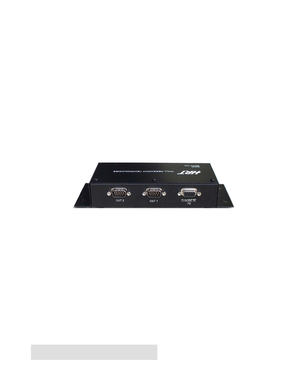
b. Attach a crossover Female-to-Female DB9 Serial cable from the OUT 1
port to the first serial device.
c. Attach a crossover Female-to-Female DB9 Serial cable from the OUT 2
port to the second serial device.
d. Connect the Discrete Outputs to any discrete devices you choose.
Pinout of the Discrete Output/Input DB9 connector
Pin 1 = Discrete Output #1
Pin 2 = Discrete Output #2
Pin 3 = Discrete Output #3
Pin 4 = Discrete Output #4
Pin 5 = Ground
Pin 6 = Discrete Output #5
Pin 7 = Discrete Input #1
Pin 8 = Discrete Input #2
Serial Hub
Operation
1. The SER-HUB-C1 Serial Control System is designed to control 2 serial devices and
up to 5 contact closure devices all with the touch of one button on a keypad. The
Serial Hub listens to the 2 KP2B-HUB keypads and when it gets a command
indicating a button was pressed, it then sends out to the first serial device the serial
string corresponding to that keypad button, a serial string to the second serial
device, and then the Discrete Output levels are set. The Serial Hub then sends 10
commands to each Keypad telling the keypad how to light each LED. All these
commands are pre-programmed into the memory of the Serial Hub using the SER-
HUB-C1 Windows™ GUI software. The Serial Hub listens to the keypads and
responds to the key pressed by reading the strings and commands out of memory
and sending them out to the correct devices.