5 rear dip switch setting – Hall Research UV232A-8S User Manual
Page 9
4 or 8 Channel Splitter PC Video, Audio & RS232 over Twisted-Pair Receivers
7
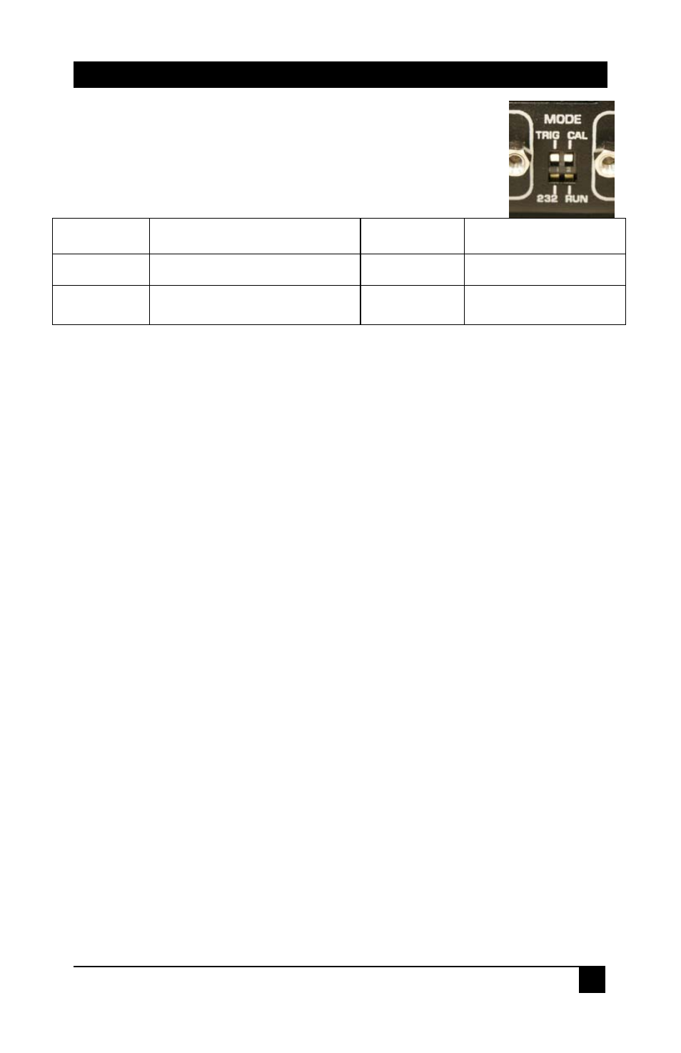
2.5 Rear DIP Switch Setting
The rear of the splitter has a DIP Switch with the following
functions:
LEFT DIP SW
FUNCTION
RIGHT DIP SW
FUNCTION
TRIG
REMOTE BUTTON TRIGGER MODE
CAL
OUTPUT TEST PATTERN
232
BYPASS OR REMOTE COMMAND
MODE
RUN
OUTPUT VIDEO INPUT
If the left rear DIP switch is in the TRIG Position, then NO serial data received by the
splitter is sent to ANY of the receiver units. The receivers must be configured for
“Remote Button Trigger” mode.
If the left rear DIP switch is in the 232 Position, then all serial data received by the
splitter is sent to ALL of the receiver units.
If the right rear DIP switch is in the CAL Position, then a VIDEO TEST Pattern is sent
to all the receiver units. This is useful when adjusting the high frequency
compensation and skew. This DIP switch should be returned to the RUN Position
when the receiver video adjustments have been completed.
If the right rear DIP switch is in the RUN Position, then the AV signal connected to
the splitter is sent to all the receiver units. This is the normal position for this DIP
switch.