3 receiver connections – Hall Research UHBX-S-PSE User Manual
Page 8
HDMI Extender with Power, IR, and RS-232
8
4.2.4 UTP (Twisted Pair Catx) Connection
The extender is designed to be used with CAT6 UTP or STP cabling.
However, CAT5e cables may be used but the maximum cable length will be
reduced by approximately 20% depending on the quality of the cable.
Augmented CAT6 cables can also be used, and are recommended for
extension distances exceeding 140 meters (or >450 feet).
T568A termination standard is recommended for the UTP cable, However
T568B will also work (as long as both ends are terminated the same way).
In EMI noisy environments (such as close proximity to power transformers
or AC wiring) shielded twisted pair (STP) cable is recommended. If STP is
used it is important to ensure the RJ45 connector on both ends of the cable
have the required metal shroud and that the cable shield/drain wire is
electrically connected to the metal shroud.
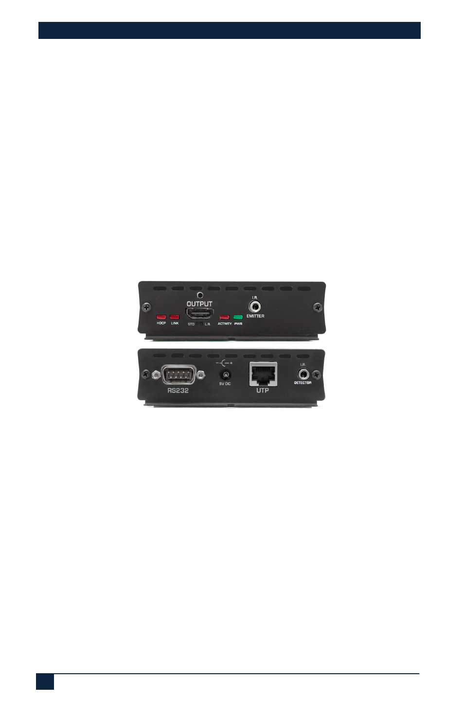
4.3 Receiver Connections
Figure 10 - Receiver Connections (UHBX-R-PSE shown above)
4.3.1 Receiver Video Output
Connect the HDMI output to the remote display's HDMI input using high
quality HDMI cables. Note that the HDMI output connector on the Receiver
has a locking nut so that compatible output cables can be positively
anchored.
4.3.2 Receiver IR, UTP, and Power Connections
Please refer to the description given in section 4.1 since these connections
work the same way on both the Sender and the Receiver.
4.3.3 Receiver Serial Connection
If required, plug DB9 RS232 cable from the Receiver to the device being
controlled (such as a projector or switcher). Pin out of the Male RS232
connector on the sender is shown below