Hall Research UHBX-S-PSE User Manual
Page 6
HDMI Extender with Power, IR, and RS-232
6
4.2.2 Sender Serial Data Connection
If required, plug DB9 RS232 cable from source to the connector on the box.
Typically a straight-through male-to-female cable is used to connect to the
sender. Pin out of the RS232 connector on the sender is shown below
DB9-F Pin
Term
Direction
2
TX
Output
3
RX
Input
5
GND
4.2.3 IR Connections
The extender can extend Infra-red Remote Control signals in both directions.
On each box two IR connectors are provided: “IR Detector” and “IR
Emitter.”
IR Detector Cable
As the names imply the IR detector jack requires connection to a compatible
IR detector cable. This device uses “pass-thru” IR detector cable that
maintains the IR modulation. Compatible cables are available from Hall
Research (Model Number CIR-DET-P2). Pin out: Tip=Data, Ring=+5V DC,
Sleeve=GND
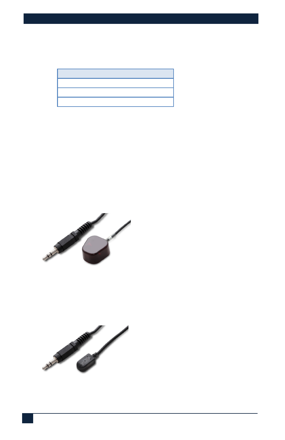
Figure 5 –
IR Detector Cable CIR-DET-P2
(Detector eye has adhesive backing)
IR Emitter (Blaster) Cables
Currently two IR emitter cables are available: CIR-EMT and CIR-EMT2.
CIR-EMT, shown below, is recommended for most applications
Figure 6 –
IR Emitter Cable CIR-EMT
(Emitter has adhesive backing)
Pin out: Tip=Anode, Ring=Cathode, Sleeve=Not Connected
An alternative Emitter cable is CIR-EMT2. This cable is better suited for
situations where there is a need to isolate and confine the IR signal to just