Hall Research UHBX-8X User Manual
Page 9
UHBX-8X
9
T568A termination standard is recommended for the UTP cable, However
T568B will also work (as long as both ends are terminated the same way).
To avoid interference with video, in EMI noisy environments (such as close
proximity to power transformers or AC wiring) shielded twisted pair (STP)
cable would be recommended. If STP is used it is important to ensure that the
RJ45 connector on both ends of the cable have the required metal shroud and
that the cable shield/drain wire is electrically connected to the metal shroud
and carried through from the sender to the receiver.
When Class-A HDBaseT receivers are used (such as Hall Research UH-1BTX-
R or UHBX-R-PD), then the signal in the UTP can be strengthened by
enabling Long Reach mode of operation. In this mode not only you can extend
the signal beyond 100 meter limit, but also the signal is more immune to noise
and interference even if the length of the cable is less than 100 meters. The
UHBX-R-PD receiver has a small switch on the box that sets its mode to either
Standard, or Long Reach, so the switch should be used to set the desired mode.
The UH-1BTX-R, does not have a mode switch, however the mode can be set
on the UHBX-8X using the Windows GUI. If you are using UH-1BTX and
would like to set the link mode to Long Reach, you can do that using the
Windows GUI through the USB connection. This is a onetime setting and the
UHBX-8X will remember the mode set for each output. Please refer to the
Windows GUI User’s Guide (available on-line) for more information.
3.2.7 Powering Receivers Using PoH (Power-over-HDBaseT)
The extender has a built-in universal power supply with a standard IEC320
C14 plug. If compatible receivers with PoH function (Such as Hall Research
UHBX-R-PD) are used with the extender, an external 48v power supply must
be plugged in to provide power to all receivers connected to the UHBX-8X.
Figure 17 –
Optional 48v Power Supply
Model: 511-PS4812
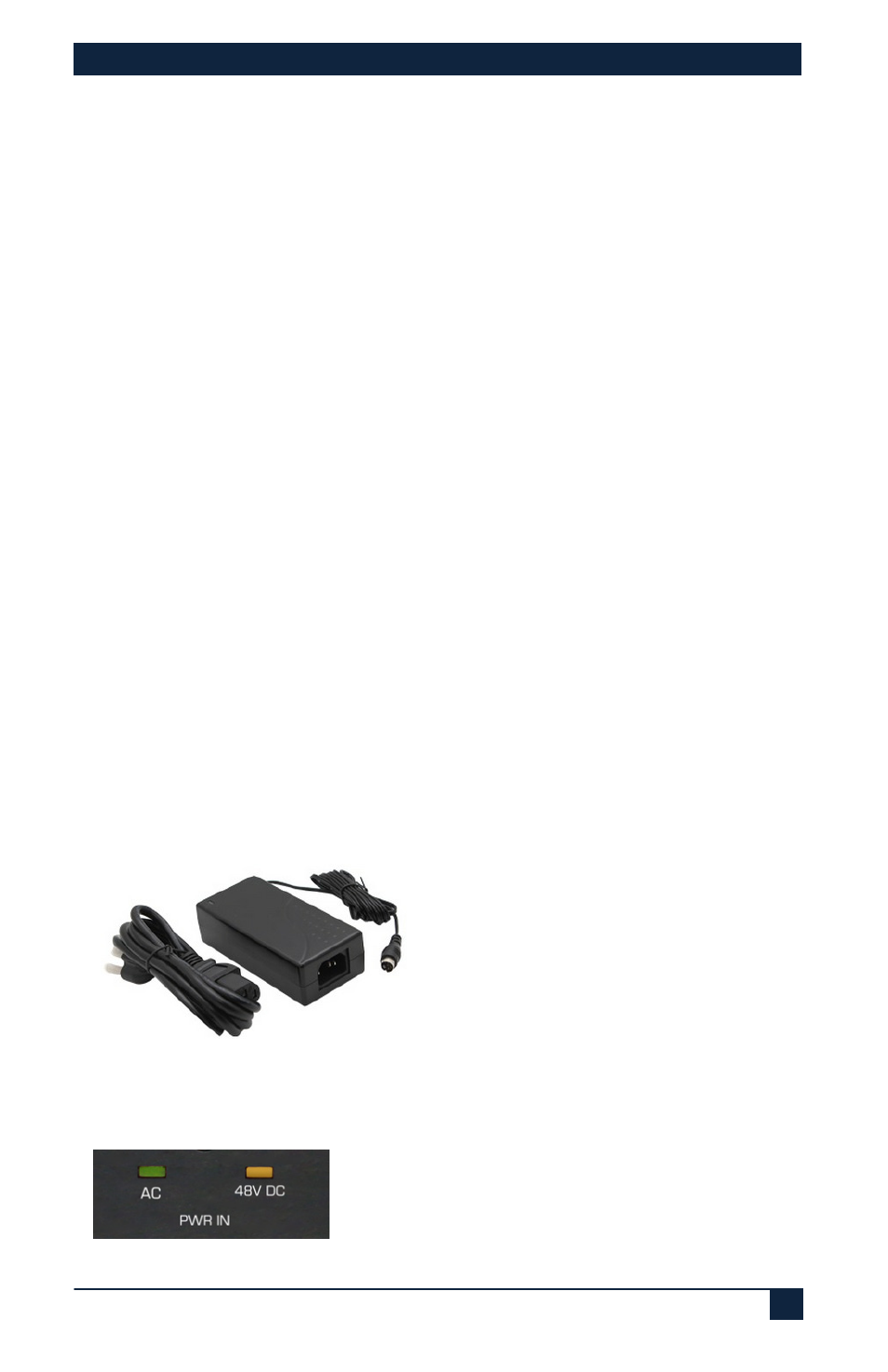
The Front panel of the UHBX-8X provides LED indicators for both AC and
the optional 48 vDC power inputs.
Figure 18 –
Front panel power indicators