0 connecting to the battery & solar array, 0 disclaimer of liability & warranty – Go Power! Solar Extreme User Manual
Page 8
8
gp
electric.com
GP-RV-80
GP-RV-95
GP-RV-160
GP-RV-80E
GP-RV-95E
GP-RV-160E
Weekender SW
Weekender HD
Solar Elite
Solar Extreme
The GP-PWM-30 provides the necessary protection for the RV battery system. A condensed version
of the installation instructions appear below. However, please read the full installation manual included
with the GP-PWM-30 Solar Controller.
1. Disconnect or cover the solar modules and disconnect the batteries before commencing the GP-
PWM-30 wiring.
2. Run the solar module power cable to the location of The GP-PWM-30.
Do not connect the wires
to the controller or the batteries. Identify the polarity of the wires located on the battery and
solar module (positive and negative). Use coloured tape or mark wire ends with tags. Contacting
the leads of the controller in reverse polarity, however brief, will cause the controller to go into lock
out mode and the solar controller will need to be reset.
3. Wire the controller according to the terminal identification on the back of controller starting with the
battery connections. Tighten the connections and then set the battery type on the controller (see
controller manual for instruction). Then connect the solar module and tighten the connections.
4. Read The GP-PWM-30 Manual prior to installing.
6.1 Mounting The GP-PWM-30 Controller
The GP-PWM-30 should be mounted in a location relatively close to the battery, but easily seen for
monitoring system operation. Wires must be run from the solar module to the controller and then to the
battery. The GP-PWM-30 is designed to be flush mounted on the side of a cabinet or wall where the
wiring can be accessed from the back. Allow two to three inches behind the unit.
The controller should
be mounted indoors, in a dry location.
1. Select a suitable location for the installation of the controller. Run the power cable from the solar
module to the location selected.
2. Use the template included in the GP-PWM-30 Manual to mark the four mounting holes and the “cutting
line for flush mounting”. Drill the mounting holes. Use a keyhole or jig saw to cut along the rectangular
outline you marked.
3. Wire the controller as shown in the GP-PWM-30 Manual. Use the leftover power cable to connect the
controller to the batteries.
4. Mount the controller to the wall using the four wood screws provided. Ensure the back of the controller
is protected from damage by any object.
7.0 Connecting to the Battery & Solar Array
It is recommended to connect directly to the battery wherever possible. You can also connect to the
converter charger where the battery positive and negative wires connect to the converter.
1. Clean all corrosion from battery terminals before proceeding. Crimp ring terminals onto the negative
and positive wires of the power cable to be attached to the battery.
2. Attach the negative (black) wire’s 3/8” ring terminal to the RV battery. Check all electrical connections
and apply a protective coating to battery terminals.
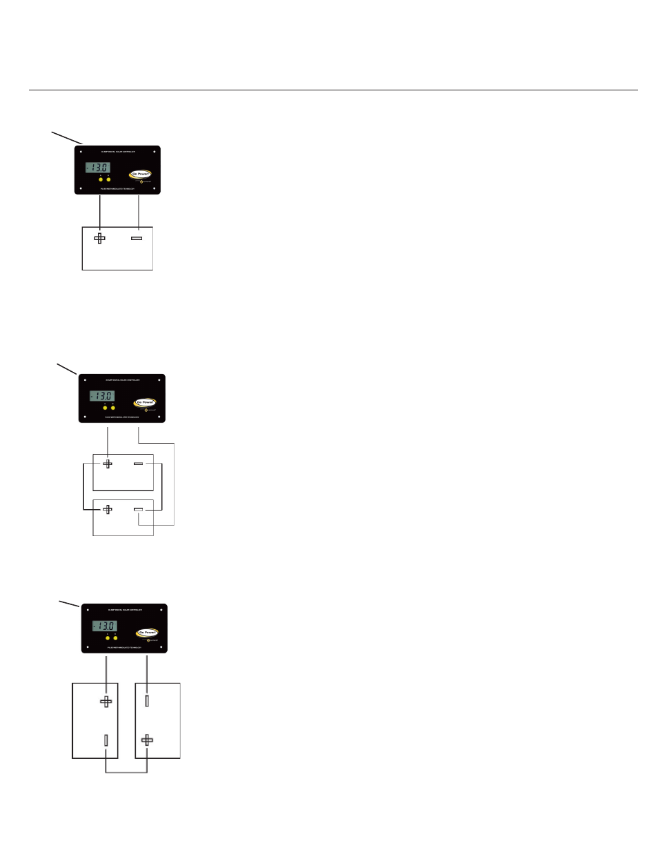
7.1 Typical Battery Connection
1. Single 12 Volt battery connection
(See Figure 5)
2. Parallel 12 Volt battery connection
(See Figure 6)
3. 6 Volt series battery connection
(See Figure 7)
8.0 Disclaimer of Liability & Warranty
1. Go Power! warrants the Go Power!
TM
RV Solar Power Kit for a period of one (1) year from the date
of shipment from its factory. This warranty is valid against defects in materials and workmanship for
the one (1) year warranty period. It is not valid against defects resulting from, but not limited to:
•
Misuse and/or abuse, neglect, or accident
•
Exceeding the unit’s design limits
•
Improper installation, including, but not limited to, improper environmental
Figure 5
Single 12 Volt Battery
12 Volt Configuration
Solar
Controller
Negative
Connection
Positive
Connection
Figure 6
Solar
Controller
Solar
Controller
Positive
Connection
Negative
Connection
Two 12 Volt Batteries
12 Volt Parallel Configuation
Figure 7
Positive
Connection
Negative
Connection
Two 6 Volt Batteries
12 Volt Series Configuation