Installation, Bd c e – Glow-worm Systempro User Manual
Page 9
0020128352_01 - 03/11 - Glow-worm
- 7 -
INSTALLATION
EN
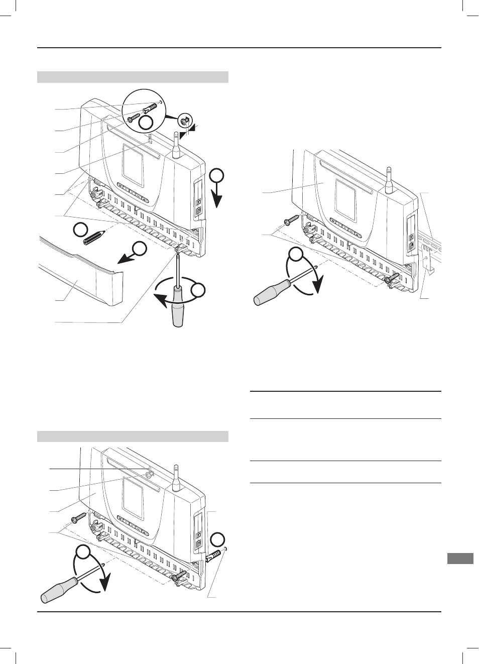
9.2.1 Wall
mounting
Step 1
B
D
C
E
5
A
1
2
3
4
5
6
7
8
Key
1 Hatch
screw
2 Control unit hatch
3 Lower attachment holes
4 Control
unit
5 Upper attachment holes
6 Upper
screw
7 Plug
8 Holes
•
Mount the appliance following the steps from (A) to (E).
•
Remove the control unit (4) by sliding along the wall.
Step 2
B
A
1
2
3
4
6
5
Key
1 Lower
screws
2 Control
unit
3 Upper
screw
4 Upper attachment holes
5 Plug
6 Holes
•
Mount the appliance following the steps from (A) to (B).
9.2.2
Mounting on DIN rail
A
1
2
3
4
Key
1 Lower
screws
2 Control
unit
3 DIN rail (not supplied)
4 DIN mounting (not supplied)
10 Electrical connections
e
Incorrect installation can cause electric shock or
damage to the equipment. The electrical connection
must be made only by a qualifi ed engineer.
•
Ensure system is electrically isolated.
•
Protect the electrical installation by following the guidance
indicated in the “Technical data” chapter.
e
Warning! The length of the power supply cable must
not exceed 10 metres.
•
The electrical installation in the dwelling must permit the
power supply to the equipment to be isolated by a double pole
isolation switch and be fused. The double pole isolation switch
must incorporate a gap of 3mm between the contacts.
•
Use a power cable suitable for the mains connection, minimum
0.75 mm. If the cable is damaged, it must be replaced by a
qualifi ed engineer.
The external wiring must be earthed. The polarity must be correct
and consistent with current standards.