Installation – Glow-worm Systempro User Manual
Page 11
0020128352_01 - 03/11 - Glow-worm
- 9 -
INSTALLATION
EN
10.2 Electrical
connections
1
3
2
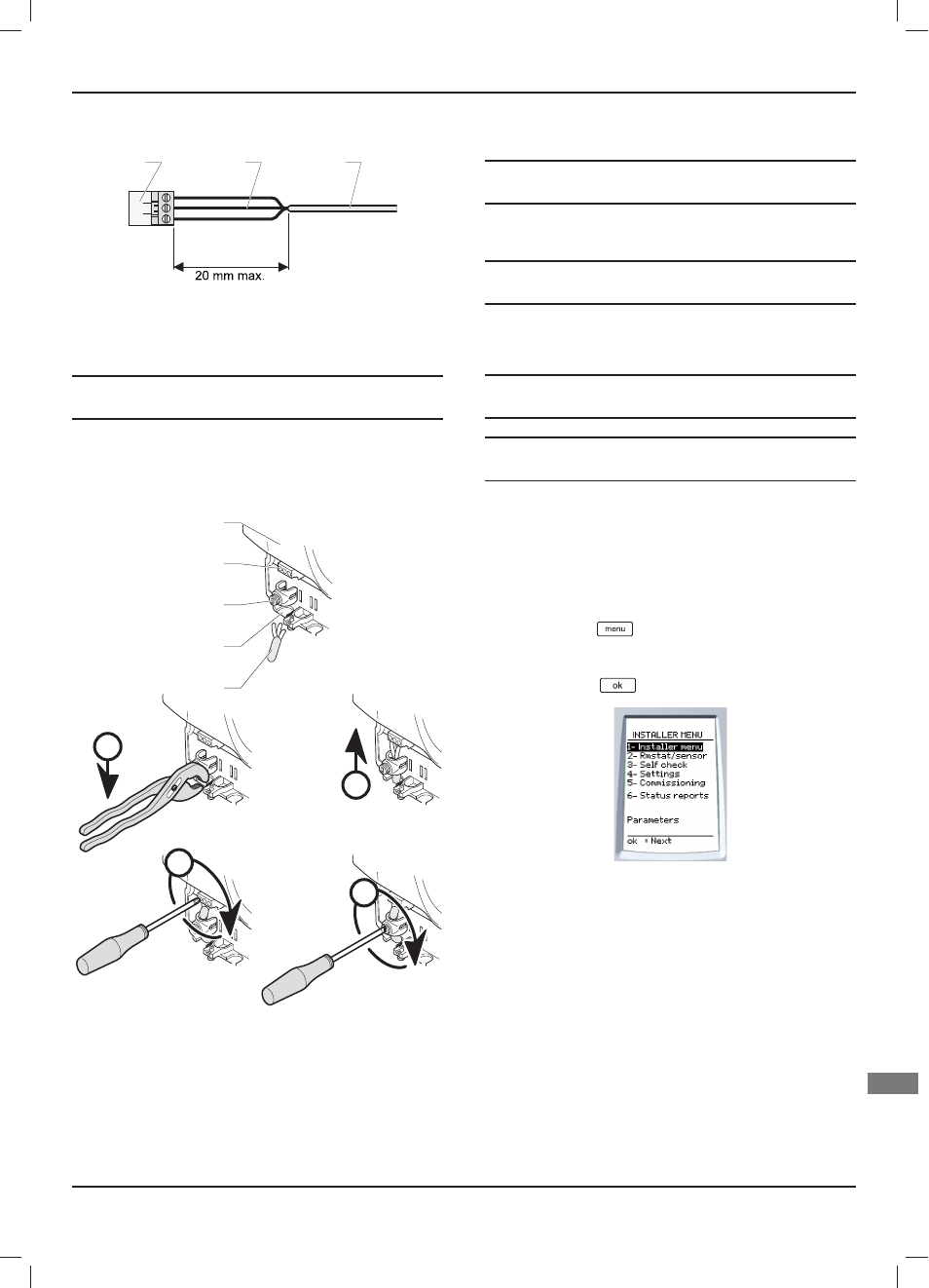
Key
1 Connector
2 Electrical
wires
3 Casing
e
Warning! When connecting electrical cables to a
connector in the control unit:
•
Maintain a maximum distance of 20 mm between the
connector (1) and the outer insulation (3).
10.2.1
230V power supply
C
B
A
D
1
2
3
4
5
Key
1 230 V power cable
2 Break out tab
3 Anti-tamper
connection
4 Power
connection
5 Control
unit
•
Connect the control unit following the order (A) to (D).
10.2.2
Other connections following the electrical
installation diagram
e
Warning! Risk of electric shock.
Break the grommets necessary for passing the cables.
•
Protect access to live parts, attach all cables to the control unit
with anti-tamper connectors.
i
Consult the system manual for electrical connections
following installation.
11 Commissioning
i
When connected for the fi rst time, the installation
menu is displayed.
i
Consult the system manual in order to install and
start-up the system.
12 Installation menu
The installation menu is still accessible after commissioning.
12.2.1
Access to the installation menu
•
Press the button
for 7 seconds.
•
Enter the installer access code 96.
•
Press the button
to confi rm.