Installation, 1 connection, 230v – Glow-worm Systempro User Manual
Page 10: Ebus, 1 external connection, 2 internal connection
0020128352_01 - 03/11 - Glow-worm
- 8 -
INSTALLATION
EN
The manufacturer declines any responsibility for damages to
persons or others caused by the incorrect installation of the
appliance earthing. This includes failure to comply with current
standards.
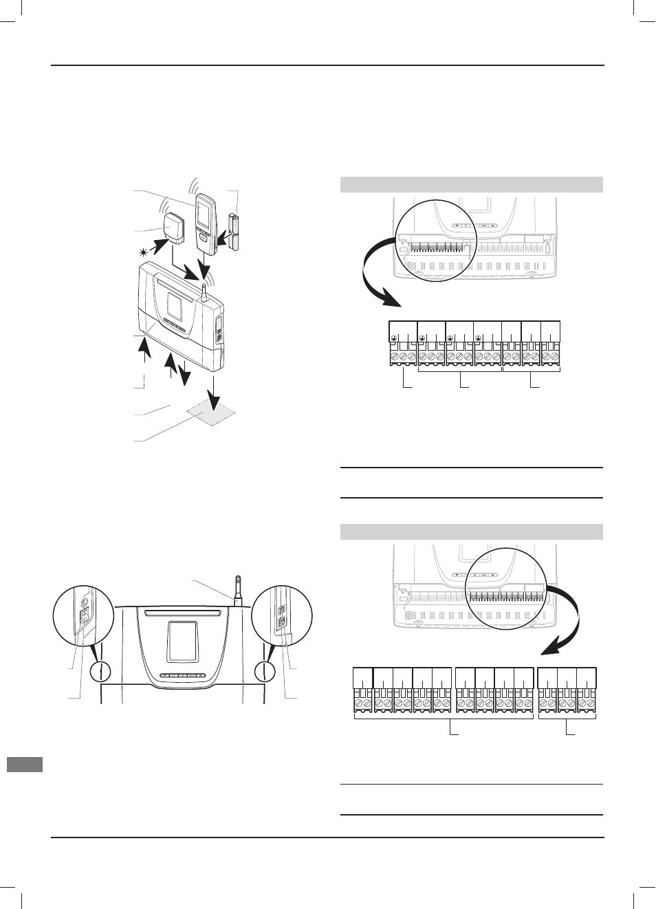
10.1 Connection
230V
IN
OUT
NTC
EBUS
1
2
3
4
5
6
7
Key
1 EBUS
connections
2 Input/Output,
sensors
3 230 V power supply
4 Control
unit
5 Outside wireless temperature sensor
6 Wireless room thermostat
7 Batteries
10.1.1 External
connection
1
2
3
5
4
Key
1 Switch On (I) / Off (O)
2 Fuse 1AT 20mm
3 Antenna
4 RJ9 EBUS socket
5 RJ11 EBUS socket
The switch (1) is employed to cut the power supply before making
any changes to the electrical connection.
The electrical circuit of the equipment is protected internally by a
fuse (2).
The antenna is used for wireless connection with the
Climapro2 RF and the outdoor sensor.
The RJ9 EBUS (4) socket is used for diagnosing the appliance.
The RJ11 EBUS (5) socket is used for connecting the EBUS
extension board.
10.1.2 Internal
connection
230V connectors
1
3
L
N
230V~
1
3
L
N
REL1
1
3
L
N
REL2
1
3
L
N
REL3
1
2
L
N
REL4
1
2
L
N
REL5
1
2
L
N
IN1
3
2
1
Key
1 230 V connector (3-pin: earth / neutral / live)
2 Connectors (3 pins: earth / neutral / live):
REL1, REL2 and REL3
3 Connectors (2 pins: live / neutral):
REL4, REL5 and IN1
i
Consult the system manual for electrical connections
following installation.
The connector (1) is employed to connect the electricity supply.
24V connectors
1
2
2
1
OUT1
1
2
2
1
OUT2
1
2
2
1
OUT3
1
2
2
1
IN2
1
2
2
1
IN3
1
2
2
1
NTC1
1
2
2
1
NTC2
1
2
2
1
NTC3
1
2
2
1
NTC4
1
2
-
+
EBUS
1
2
-
+
EBUS
1
2
-
+
EBUS
2
1
Key
1 Connectors (2 pins)
OUT1, OUT2, OUT3, IN2, IN3, NTC1, NTC2, NTC3 and NTC4
2 EBUS connectors (2 pins)
i
Consult the system manual for electrical connections
following installation.