3 flue and ventilation, Back boiler unit – Glow-worm Inset 40BBU User Manual
Page 7
7
221722B
BACK
BOILER
UNIT
3 Flue and Ventilation
Diagram 3.1
3.1 General
The general recommendations of the current issue of BS5440
Part 1 should be followed.
In all cases the flue should be lined, preferably with a flexible
liner.
It is essential that the flue has an equivalent height of at least
2.5m (8.2ft) measured from the flue connection on the appliance.
The first 600mm, at least, above the draught diverter must be
vertical.
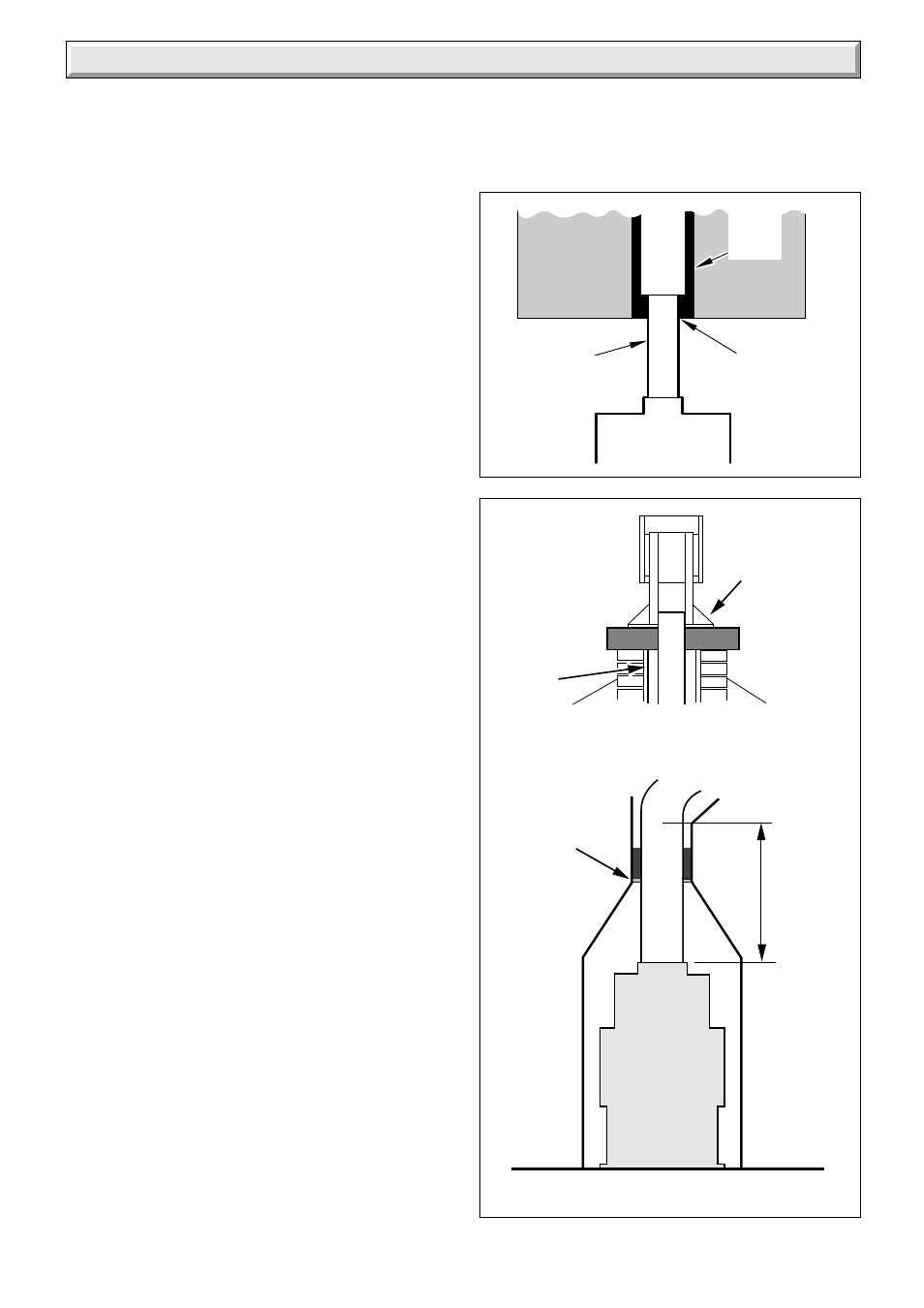
Where the installation is new it is essential to make sure that the
annular space between the boiler flue liner and the chimney is
sealed at the base and at the top of the chimney, as shown in
diagram 3.2.
The flue socket is designed to take flue pipe to BS567. If flue
pipe conforming to a different standard is used a suitable
adapter must be fitted and secured to the flue socket. A flexible
flue liner may be used, with connection to the back boiler flue
socket, see diagram 3.1
The existing flue may not be completely sound. Therefore, to
prevent the possibility of leakage to an adjacent flue, additional
sealing MUST be carried out between the base of the chimney
and the flue liner.
The end of the flue liner at the chimney top must be adequately
sealed and clamped, using proprietary fittings suitable for the
flue liner used, see diagram 3.2.
The flue should, preferably, end above ridge height but at the
least above the eaves of a pitched roof. Use a certificated
terminal.
If the flue is to pass through or near any combustible material it
should be installed in accordance with the current issue of
BS5440 Part 1. If in doubt seek advice from the local gas
undertaking or Hepworth Heating Ltd.
3.2 Existing Chimney
An existing brick chimney must be thoroughly swept and all
debris cleared away before lining.
Remove any damper or register plate. Alternatively it may be
locked in the open position,
A flexible flue liner is preferred but a rigid liner may be used, with
connection to the back boiler flue socket made with a short
vertical piece of flexible liner, see diagram 3.1.
Any air supply that enters the builder’s opening other than by the
front opening, that is underdraught openings and the like must
be completely sealed off.
The sealing plate also prevents debris falling and gives the flue
better insulation, reducing the possibility of condensation, see
diagram 3.2.
Check the flue system efficiency before installing the back
boiler.
3.3 New Chimney
A newly built chimney can be lined with a moisture resistant
lining, such as salt glazed pipe, of an appropriate diameter as
specified in the Building Regulations
In the case of a salt glazed lined flue, it is recommended that a
short vertical length of flue pipe, preferably flexible metallic be
used. Fix and seal it to the back boiler flue socket, make good
with approved packing and parge with fire cement, see diagram
3.1.
If a flue and false chimney breast are to be constructed all
openings for pipework to upper floors etc., must be sealed. The
only opening for the back boiler must be at the front, being of the
dimensions as shown in diagram 1.2.
If a specially built compartment is constructed for the back
boiler, it must conform to the requirements of the current issue
of BS5440 Part 1 and BS5871.
The flue should, preferably, end above ridge height but at least
above the eaves of a pitched roof. Use a certificated terminal.
1593
APPROVED
SEAL
FLEXIBLE
LINER
BACK BOILER
RIGID
FLUE
LINER
Diagram 3.2
6197
SEALING AND
CLAMPING
PLATE
AIR
SPACE
150mm (6in) plug of Mineral Wool or similar
600mm
SEALING
PLATE