8 servicing – Glow-worm Inset 40BBU User Manual
Page 19
19
221722B
8 Servicing
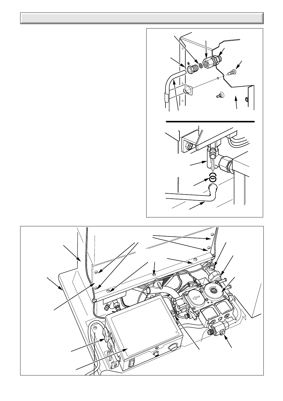
8.3 Controls Assembly and Burner.
Disconnect the union at the gas service cock, see diagram 8.2.
Remove the thermostat phial and overheat cut-off device phial
if fitted (sealed systems only), from the phial pockets, unclip the
capillary tubes, see diagram 5.4.
Disconnect the mains electrical plug from the control box, see
diagram 8.2.
Remove the four combustion chamber securing screws.
Remove the gas manifold securing screw and slide the control/
burner assembly forwards to remove, see diagram 8.2.
8.4 Burner
Disconnect the pilot tube nut and the thermocouple nut from the
gas control valve, see diagram 8.3.
Disconnect the ignition lead at the electrode.
Remove the extended screws which locate the gas manifold to
burner, see diagram 8.3.
The control box and gas control valve can now be lifted clear of
the burner.
Clean the burner as necessary, do not use a brush with metallic
bristles.
8.5 Lint Arrester
Remove the four securing screws to disengage the two lint
arresters, see diagram 8.4.
Clean the lint arresters as required.
Diagram 8.1
6300
FILTER
SENSING TUBE
FITTING
SECURING
SCREW
SENSING TUBE
“O” RINGS
SENSING TUBE
DRAUGHT
DIVERTER
FLUE BLOCKAGE
SAFETY DEVICE
TUBING
NUT
RETAINING NUT
Diagram 8.2
6205
CONTROL BOX
GAS
CONTROL
VALVE
COMBUSTION
CHAMBER
GAS SERVICE
COCK
FIRE FRONT GAS
SERVICE COCK
MAINS
ELECTRICAL
PLUG
FLOOR
PROTECTION
PLATE
COMBUSTION CHAMBER
SECURING SCREWS (4)
GAS
MANIFOLD
SECURING
SCREW
COMBUSTION
CHAMBER
FRONT COVER
UNION
BURNER SECURING
SCREWS (3)