10 replacement of parts – Glow-worm Inset 40BBU User Manual
Page 25
25
221722B
Diagram 10.6
6199
10 Replacement of Parts
LOCKOUT
RESET
BUTTON
ELECTRICAL
PLUG
RELEASE
TABS
Diagram 10.7
6683
IGNITION
LEAD
ELECTRICAL
PLUG (4)
MAINS
TERMINAL
STRIP
CONTROL
BOARD
(PCB)
SUPPORT (4)
FRONT VIEW
SHOWING HOLE IN
FRONT OF
CONTROL BOX
HOLE IN FRONT
OF CONTROL BOX
ELECTRICAL
PLUG
EARTH
LEAD
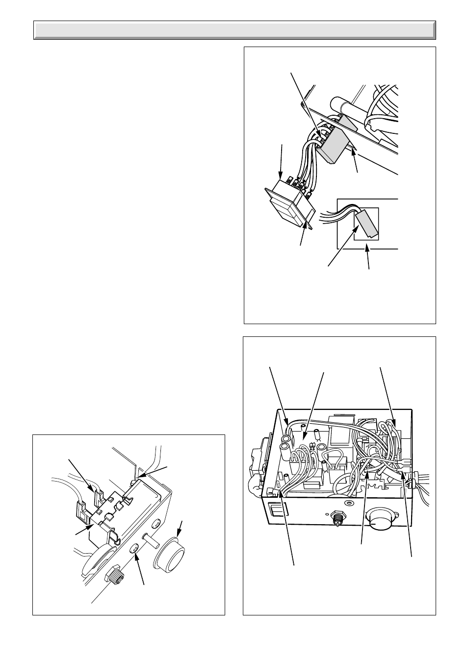
Diagram 10.4
6195
CONTROL
KNOB
ELECTRICAL
CONNECTIONS
(2)
CONTROL
THERMOSTAT
SPLIT
GROMMET
SECURING
SCREWS
10.6 Gas Valve
Refer to the relevant parts of Section 8.3 to remove the controls
assembly.
Refer to diagram 10.2.
Disconnect electrical plug.
Disconnect the thermocouple nut at the gas valve and ease out.
Disconnect interrupter electrical connections.
Disconnect the pilot tubing nut at the gas valve.
Undo the securing screws to separate the valve from the supply
pipe flange and gas manifold.
Note. When replacing the thermocouple only tighten the nut a
quarter turn beyond finger tight.
Fit the new “O” ring seals supplied with the new gas control
valve.
Should the solenoids require replacing, refer to Section 10.12.
10.7 Burner
Follow the relevant instructions in Section 8.3 and 8.4 to remove
the burner.
Transfer the flue blockage safety device to the new burner, see
diagram 10.1.
10.8 Control Thermostat
Remove the control thermostat phial and unclip the capillary
tube, see diagram 5.4.
Remove the electrical control box lid securing screw and lift the
lid back to release the rear hook, see diagram 10.3.
Remove the control knob, see diagram 10.4.
Remove the two electrical connections from the thermostat, see
diagram 10.4.
Remove the two securing screws and remove the control
thermostat and capillary from the split grommet, see diagram
10.4.
Note: When fitting the new control thermostat, make sure that
the capillary connection to the thermostat is placed at the
bottom of the control box.
Refit the electrical connections.
The capillary should pass through the split grommet on the
control box.