9 fault finding – Glow-worm Inset 40BBU User Manual
Page 23
23
221722B
9 Fault Finding
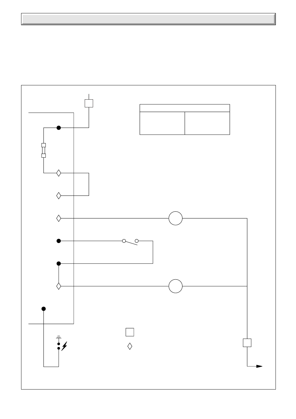
Diagram 9.2
FUNCTIONAL FLOW
7427
br BROWN
b
BLUE
w WHITE
KEY
bk BLACK
or ORANGE
3 WAY SOCKET CONNECTIONS
PCB CONNECTIONS
SPARK
ELECTRODE
HV
CN4
CN3 EV2
TH
FUSE
TYPE
F1A
br
b
N
L
bk
w
w
CONTROL THERMOSTAT
PILOT SOLENOID
LINK (OVERHEAT THERMOSTAT
IF FITTED)
MAIN SOLENOID
br
b
b
or
TH
CN3 EV1
CN5
N
9.2 Thermocouple
To test the thermocouple, a meter with a range of
0 - 30mV is required together with a thermocouple interrupter
test unit.
9.3 Electrical Fault Finding Back Boiler
Refer to diagram 9.1.
9.4 Flue Blockage Safety Device and Ignition
Fault Finding
To check the safety device and ignition, refer to fault finding
chart, diagram 9.1.
See also other documents in the category Glow-worm Water boiler:
- 12-38hxi Range (44 pages)
- 18-30sxi Range (48 pages)
- 23c (44 pages)
- 24-38CXI Range (52 pages)
- 30ci Plus (56 pages)
- BBU 45/4 (32 pages)
- BBU 54/4 (32 pages)
- Betacom C (68 pages)
- Betacom2 (8 pages)
- Betacom2 (20 pages)
- Betacom2 (56 pages)
- Black Beauty 4 (20 pages)
- Chatsworth 4 (24 pages)
- Clearly Heat Recovery (20 pages)
- Clearly Heat Recovery (32 pages)
- Clearly Heat Pumps Envirosorb3 (28 pages)
- Clearly Heat Pumps Envirosorb2 (44 pages)
- Clearly Heat Pumps 7kW (44 pages)
- Clearly Heat Pumps 5kW (28 pages)
- Clearly Heat Pump 5kW (16 pages)
- Clearly Heat Pump 5 kW (32 pages)
- Clearly Heat Pump - Buffer Vessel (10 pages)
- Clearly Heat Pumps - Standalone Module System (40 pages)
- Clearly Heat Pumps - Standalone System (28 pages)
- Clearly Hybrid - Universal Module (20 pages)
- Clearly Hybrid - Universal Module System (36 pages)
- Clearly Hybrid - Compact Hydraulic Module (12 pages)
- Clearly Hybrid - Compact System (36 pages)
- Clearly Hybrid - Compact Hydraulic Module HB (16 pages)
- Clearly Hybrid - Back-up Module System (40 pages)
- Clearly Solar System Hydraulics (28 pages)
- Clearly Solar System (28 pages)
- Clearly Solar Controller (28 pages)
- Clearly Solar Horizontal On-Roof Collector (16 pages)
- Clearly Solar Vertical On-Roof Collector (16 pages)
- Clearly Solar Cylinders (32 pages)
- Clearly Solar - A-Frame (28 pages)
- Clearly Solar Horizontal In-Roof Collector (32 pages)
- Clearly Solar Vertical In-Roof Collector (44 pages)
- Clearly Solar Collector Container (8 pages)
- Climapro 1 (12 pages)
- Climapro2 RF (16 pages)
- Climapro2 RF (24 pages)
- Climapro2 RF (36 pages)
- Climapro2 RF (32 pages)