Maintenance, 12 silencer assembly (front), 13 condensate trap – Glow-worm Flexicom cx User Manual
Page 42: 14 heating flow thermistor, 15 heating return thermistor, 18 domestic hot water thermistor, 19 plate-to-plate heat exchanger
0020107232_03 - 12/14 - Glow-worm
MAINTENANCE
- 42 -
13060
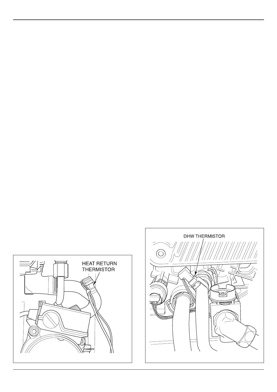
Diagram 14.4
14.12 Silencer Assembly (front)
For access, refer to section 14.1.
Pull forwards to remove.
The silencer is a push fit so no tools or fixings are required for
its removal or fitting, see diagram 12.8.
14.13 Condensate Trap
For access, refer to section 14.1.
Remove the drain outlet pipe from the base of the trap. Remove
the condensate drain securing screw and carefully pull the trap
forward, see diagram 12.13.
On the condensate trap there is a key symbol that should be
in line with the locked padlock symbol on the condense drain.
To remove the trap turn in the direction indicated, see diagram
12.13, toward the unlock symbol and carefully pull down clear of
the condense drain.
Remove any solids found in the condense trap.
Flush water through the trap to remove any remaining solids.
Check for any debris in the outlet pipe of the condensate drain
and clean as necessary.
Reassemble and refit the condense trap.
14.14 Heating Flow Thermistor
For access refer to section 14.1.
Remove the silencer front, fan/gas valve assembly and flue
hood for access. See relevant sections.
Refer to diagram 14.3.
Remove the electrical connections from the thermistor.
Remove the retaining clip from the flow pipe.
Remove the thermistor from the retaining clip.
Note that the polarity of the wiring to thermistors is unimportant.
14.15 Heating Return Thermistor
For access, refer to section 14.1.
Refer to diagram 14.4.
Remove the electrical connections from the thermistor.
Remove the retaining clip from the return pipe.
Remove the thermistor from the retaining clip.
Note that the polarity of the wiring to thermistor is unimportant.
Note that the polarity of the wiring to thermistor is unimportant.
14.18 Domestic Hot Water Thermistor
For access, refer to section 14.1.
Refer to diagram 14.5.
Remove the electrical connections from the thermistor.
Remove the retaining clip from the DHW pipe.
Remove the thermistor from the retaining clip.
Note that the polarity of the wiring to thermistor is unimportant.
14.19 Plate-to-Plate Heat Exchanger
For access, refer to section 14.1.
Drain the boiler heating circuit, refer to section 14.1.
Refer to section 14.3 and drain the boiler hot water circuit.
Refer to diagram 14.6.
Remove the gas supply pipe from the gas service isolation
valve and the gas valve, refer to relevant parts of section 14.4.
Remove the condensate trap as described in section 14.13.
Remove the four screws securing the plate-to-plate heat
exchanger to the hydroblock, see diagram 14.6.
Remove the plate-to-plate heat exchanger.
When replacing the plate-to-plate heat exchanger ensure that
the four rubber sealing washers are fitted into the hydroblock.
NOTE: The plate-to-plate heat exchanger only fits one way
round.
Refill, vent and pressurise the boiler.
Open the cold-water isolation valve and slowly open a hot water
tap to remove air.
Close the hot water tap and check for any leaks.
Open the heating circuit isolation valves, re-pressurise the
system as necessary, refer to diagram 14.1.
13063
Diagram 14.5