Maintenance, 12 servicing general inspection – Glow-worm Flexicom cx User Manual
Page 29
0020107232_03 - 12/14 - Glow-worm
MAINTENANCE
- 29 -
IMPORTANT NOTES:
1. To ensure the continued efficient and safe operation of the boiler it is recommended that it is checked and serviced at
regular intervals. The frequency of servicing will depend upon the particular installation and usage, but in general once a
year should be enough.
2. It is the Law that any servicing is carried out by a
competent person approved at the time by the Health and Safety
Executive
.
3. Before commencing with a service or replacement of parts the boiler should be isolated from the electrical supply and the
gas supply should be turned off at the gas isolation valve.
4. When replacing a part on this appliance, use only spare parts that you can be assured conform to the safety and
performance specification that we require. Do not use reconditioned or copy parts that have not been clearly authorised
by Glow-worm.
5. If any electrical connections have been disconnected and after their connection, checks to the earth continuity, polarity,
short circuit and resistance to earth must be repeated using a suitable multimeter, as described in section 13.
6. After servicing, complete the relevant Service Interval Record section of the Benchmark Checklist located in the inside
back pages of this document.
12 Servicing
General Inspection
Prior to, during servicing and after any maintenance or changed
parts, the following must be checked.
● The integrity of the flue system and flue seals.
● The integrity of the appliance combustion circuit and
relevant seals.
● Electrical, gas and water connections.
● System pressure.
● the combustion performance, refer to the following procedure.
● The operational gas inlet pressure and gas rates, refer to the
commissioning section paragraph 11.7.
Correct any fault before continuing.
COMPETENCY TO CARRY OUT THE CHECK OF
COMBUSTION PERFORMANCE
NOTE: BS 6798: 2009 Specification for installation and
maintenance of gas-fired boilers of rated input not exceeding
70kW net advises that:
● The person carrying out a combustion measurement must
be assessed as competent in the use of a flue gas analyser
and the interpretation of the results.
● The flue gas analyser used should be one meeting the
requirements of BS7927 or BS-EN50379-3 and be calibrated in
accordance with the analyser manufacturers’ requirements.
● Competence can be demonstrated by satisfactory completion
of the CPA1 ACS assessment, which covers the use of
electronic portable combustion gas analysers in accordance
with BS 7967, parts 1 to 4.
● Ensure that the gas analyser is set to the correct fuel
setting.
● Select the “
°C
bar
°C
bar
”, constant central heating with DHW
function by pressing the “Mode” button repeatedly, refer to
commissioning section.The boiler should fire automatically.
NOTE: Safe combustion can only be verified by measuring CO/
CO2 ratio. This must not exceed the value shown in the table
below.
Diagram 13.1
15445
G20 BURNER % CO
2
MODEL
CHECK
SETTING
CO/CO
2
ratio
24cx
8.8 to 9.8
9.2 +0.3
- 0.3
0.004
30cx
8.8 to 9.8
9.1 +0.3
- 0.3
0.004
35cx
8.8 to 9.8
8.8 +0.3
- 0.3
0.004
COMBUSTION CHECK AND SETTING THE AIR/
GAS RATIO VALVE
● Remove the front casing panel, see diagram 12.2 and hinge
down the control box. Taking care not to touch any internal
components, proceed as follows:
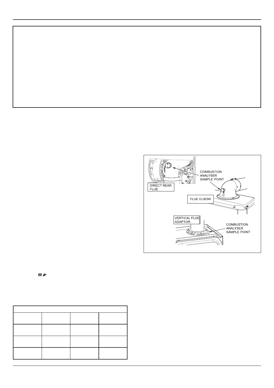
● Connect the CO2 combustion analyser to the relevant test
point, see diagram 12.1.
1. Maximum Rate Check and Adjustment
NOTE: To verify the maximum gas rate CO2 setting the
appliance must be checked at the maximum rate first. Press the
“reset” button on the controls fascia, release and
immediately press and hold in the “+” button. After
approximately 5 seconds “Hi” will be displayed. Pressing
the mode button when “Hi” is selected will force the boiler
to maximum rate, the display will flash between “Hi” and the
“default display” this will indicate the boiler has been forced to
maximum. Wait until the CO2 value is stable and check that
the value is within the range specified in table in the “check”
column.
If the combustion reading is not within the acceptable values
AND the integrity of the complete flue system and combustion
circuit seals have been verified and the inlet gas pressure
(and gas rate) have been verified, then, it will necessary to
adjust the combustion rate of the appliance.
NOTE: Adjustment is made by turning the gas valve throttle
an ⅛ of a turn, waiting 1 minute to allow the appliance to
stabilise before checking or making further adjustments.