Installation, 5 water systems - domestic hot water 5.4 general, 5 water pressure – Glow-worm Flexicom cx User Manual
Page 16: 6 ‘hard’ water areas, 7 domestic water flow rate, 9 bypass, 10 safety valve
0020107232_03 - 12/14 - Glow-worm
INSTALLATION
- 16 -
5 Water systems - Domestic Hot Water
5.4 General
All domestic hot water circuits, connections, fittings must be
in accordance with the relevant standards and water supply
regulations.
For GB: Guidance G17 to G24 and recommendation R17 to
R24 of the Water Regulations Guide
(for Scotland, the Water
Byelaws 2000, Scotland)
.
For IE: The current edition of I.S.813 “Domestic Gas
Installations”.
5.5 Water Pressure
The minimum working pressure to obtain the maximum
domestic flow is:-
24cx 1.0bar
30cx 1.0bar
35cx 1.0bar
The maximum working pressure of the domestic hot water
circuit is 10 bar. If the cold water supply pressure exceeds this,
then a pressure-reducing valve must be fitted in the supply to
the boiler.
5.6 ‘Hard’ Water Areas
The temperatures within the heat exchanger are limited by the
boiler control system to minimise scale formation within the hot
water pipework. However, in areas where the water is ‘hard’ (i.e.
more than 200mg/litre), it is recommended that the hot water
setting is reduced and that a scale reducer is fitted, refer to the
manufacturer’s instructions or consult the local water company
for additional advice.
5.7 Domestic Water Flow Rate
The water flow rate is restricted to a maximum 9.4 l/min for
24cx, 11.7 l/min for 30cx and 13.0l/min for 35cx by a restrictor
factory fitted within the boiler.
15725
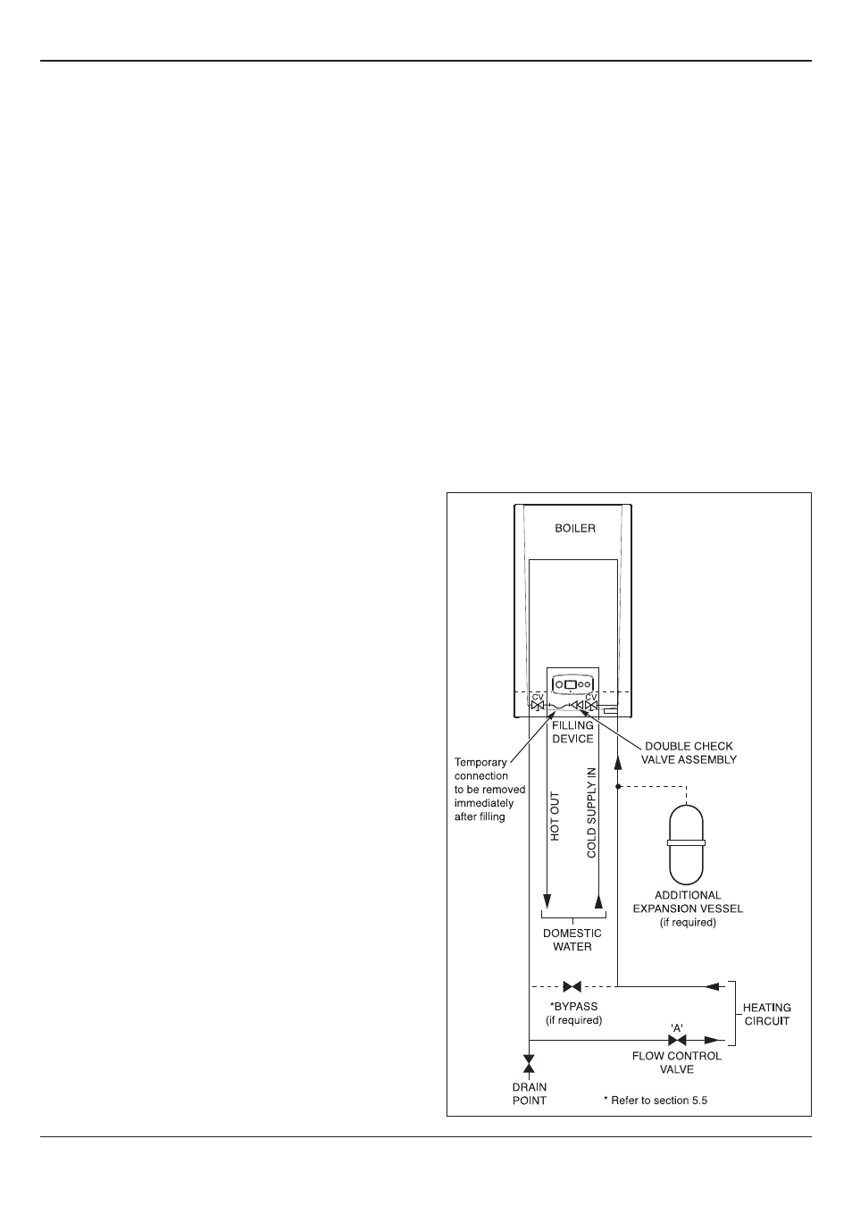
Diagram 5.3
5 Water Systems - Sealed Central Heating
system
5.8 Flow Rate
If it is necessary to alter the flow rate, the system can be fitted
with a lockable balancing valve in the main flow or return pipes
shown as valve “A” in diagram 5.3. The flow rate through the
boiler must not be allowed to fall below that given in section 1 -
Specification Table.
5.9 Bypass
The boiler is fitted with an automatic bypass.
Diagram 5.2 shows the pump head remaining for the heating
system depending on the bypass setting and the speed setting
of the pump, see section 11 Commisioning.
Ensure that under no circumstances does the flow rate drop
below the figure specified, refer to section 1 - Specification
Table and section 11.9.
5.10 Safety Valve
The safety valve is an integral part of the boiler and it cannot
be adjusted.
The pipe from the safety discharge valve must
not discharge above an entrance, window or any type of public
access area.