14 replacement of parts – Glow-worm Compact 80E User Manual
Page 34
34
221742D
14 Replacement of Parts
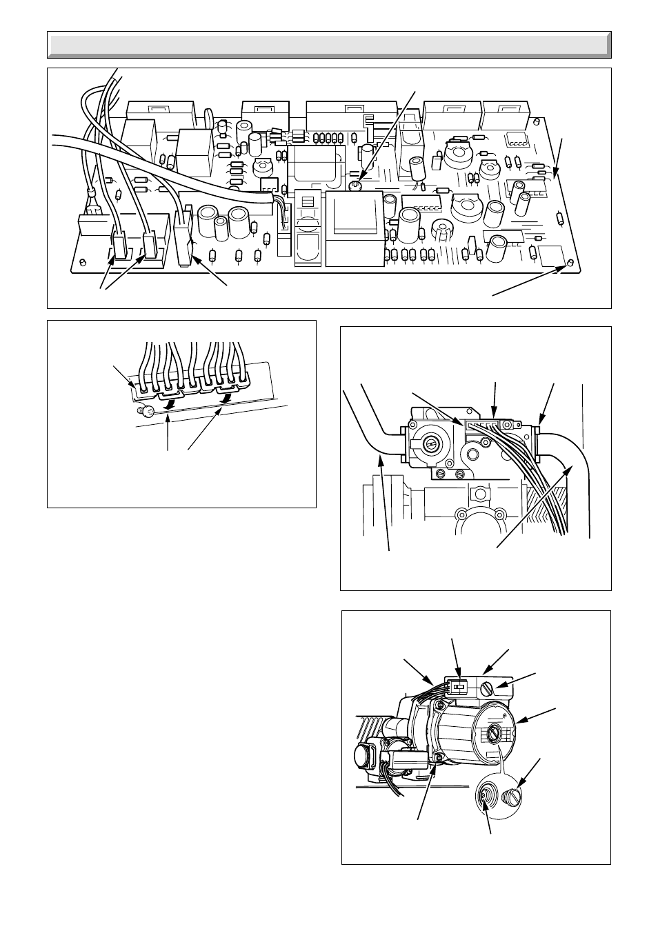
Diagram 14.8
6982
CONTROL
BOARD
SENSING
LEAD
SUPPORT
POSTS (4)
Diagram 14.9
SOCKET
HEAD
CAPSCREW
(8)
GAS SUPPLY
PIPE)
GAS
CONTROL
VALVE
6986
MANIFOLD
MULTI PIN
CONNECTOR
14.11 Low Water Pressure Switch
Before starting refer to Section 11.
Remove the two screws securing the controls cover door and
controls fascia, see diagram 9.1.
Hinge the assembly open.
Release the water pressure and drain the central heating circuit
of the boiler, refer to Section 11.3 and 11.6.
Remove the clip to remove the water pressure switch, see
diagram 14.11.
Remove the plastic cover.
Remove the electrical connectors.
Refer to wiring diagram 14.29 when fitting.
14.12 Safety Valve
Before starting refer to Section 11.
Remove the two screws securing the controls cover door and
controls fascia, see diagram 9.1.
Hinge the assembly open.
Remove the case base, see diagram 10.3.
Release the water pressure and drain the central heating circuit
of the boiler, refer to Section 11.3 and 11.6.
Disconnect the union nut and clip to release the safety valve,
see diagram 14.5.
Diagram 14.10
ELECTRICAL
SUPPLY
LEADS
SPINDLE
6988
PUMP
PLUG
END
SCREW
TERMINAL
COVER SCREW
PUMP
ADJUSTER
SECURING
SCREW 4)
7244
Diagram 14.7
SECURING SCREW
CAREFULLY BEND THE
RETAINING CLIPS FORWARD
TO RELEASE MULTI PIN
CONNECTORS
MULTI PIN
CONNECTORS
IGNITION LEADS