12 servicing, 13 fault finding – Glow-worm Compact 80E User Manual
Page 27
27
221742D
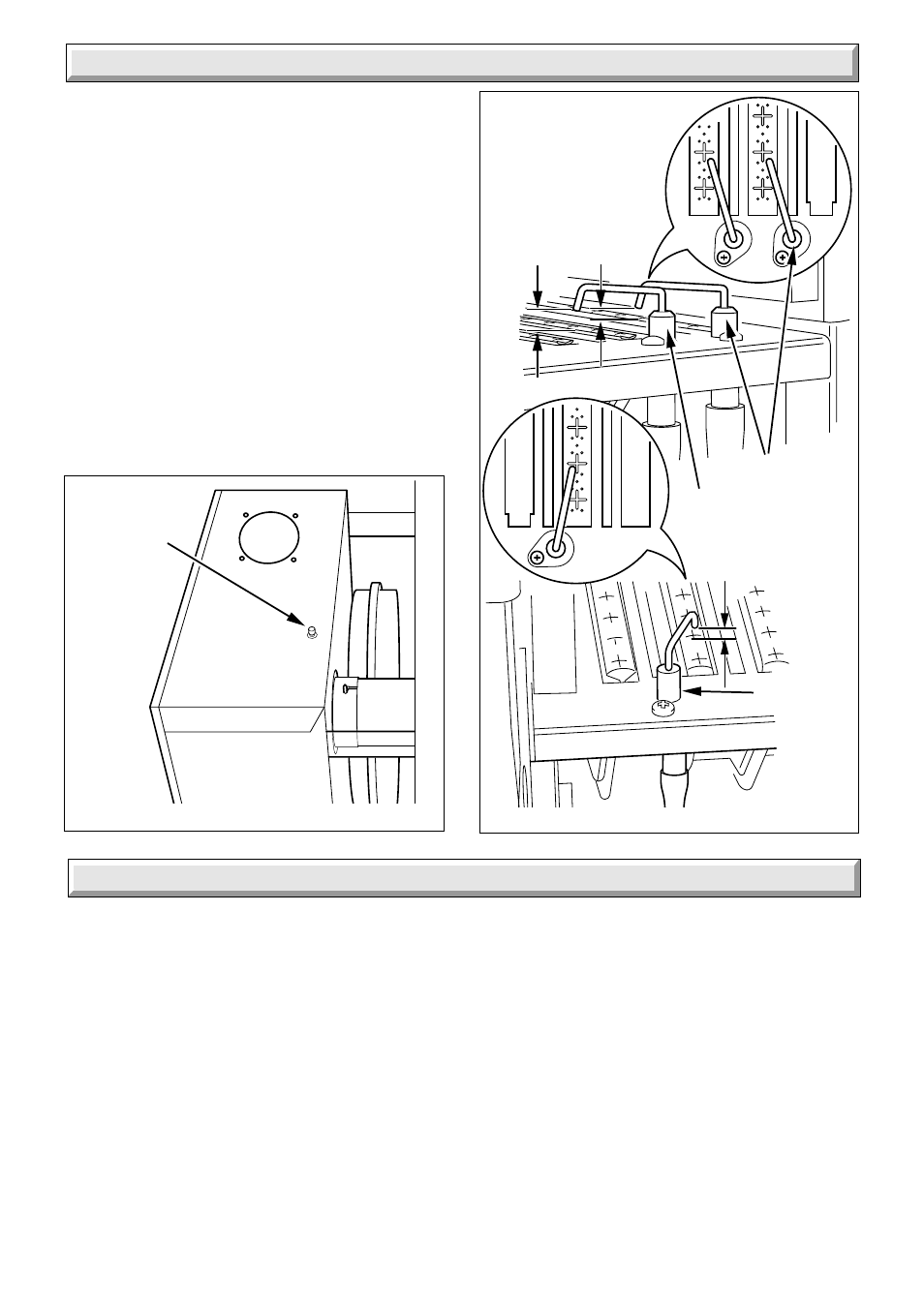
12.6 Spark Gap
Check that the spark and sensing gaps are as shown in diagram
12.6.
12.7 Operational Checks
Light the boiler, carry out operational checks and any necessary
adjustments as described in “Commissioning” in the Installation
Instructions.
12.8 Completion
Slide the outer case front on secure with the nuts previously
removed.
7647
Diagram 12.6
SPARK GAPS
12 Servicing
SENSING
ELECTRODE
IGNITION
ELECTRODE
1.5mm
- 2mm
13 Fault Finding
7076
PRODUCTS
PROBE
Diagram 12.7
13.1 Initial Checks
If the boiler fails to operate, first check the following:-
1) That the electrical supply is available at the boiler and the
fuses are in order.
NOTE: THE BOILER CONTROL BOARDS CAN BE DAMAGED
BY INCORRECT TESTING OF COMPONENTS AND WIRING
WITH THE POWER ON.
2) Make sure that the system pressure gauge registers 0.7bar,
minimum, and that the automatic air vent works. Refer to
Installation Instructions, Section 10.2.
3) That the gas supply is available at the boiler and purged of
air.
4) That the boiler is set for the required service.
5) With the boiler Summer/Winter Button “J” set to summer “L”,
see diagram 4 User Instructions, check that the domestic water
supply is available and water flows freely from the hot taps.
Close the taps.
6) With the boiler Summer/Winter Button “J” set to Winter “K”,
see diagram 4 User Instructions, check that all heating system
controls, if fitted, are working correctly and calling for heat. If not
isolate the boiler from the electrical supply.
Test for continuity, at mains.
7) Check Summer/Winter Button “J” is set to Winter, see
diagram 4 User Instructions. In certain circumstances the red
neon light may not come on, due to no system demand. Turn on
a domestic hot water draw off tap to create a demand.
Allow the boiler and system to cool down waiting at least a
minimum of four minutes before pressing Summer/Winter Button
“J” to set to Winter “K”.
If this is satisfactory proceed with the detailed fault finding as
Section 13.3.
IGNITION
ELECTRODE
1.5mm
- 2mm
4mm