4 installation - controls, 7 installation of the remote control, 8 electrical connection of the remote control – Glow-worm Clearly Heat Recovery User Manual
Page 15
15
4 Installation - Controls
4.7 Installation of the Remote Control
Site the remote control on an inside wall at a height of about
1.5 m, were the controller is able to detect the circulating
ambient air clearly and unimpeded from furniture, curtains or
other external influences. The position should be selected so
that neither air drafts from the door or the window nor heat
sources such as radiators, TV or solar irradiation may directly
influence the controller.
A connection with the ventilation unit is established via a
2-core connection cable.
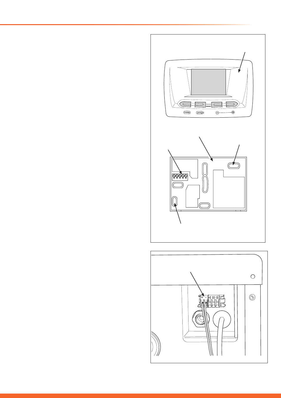
Pull the remote control from the wall base.
Refer to diagram 4.7.
With due regard to the position of the cable entry, mark the
wall base securing points on the wall. Using a 6mm diameter
drill and fixings supplied, secure the wall base to the wall
having first pulled the cable through the cable entry.
Connect the cable to the corresponding terminals (eBUS “+”
and “-”) on the terminal connecting strip.
Place the control on to the wall base such that the pins at the
back of the upper part locate into the seats.
Press the casing to the wall base till it locates, taking care not
to bend the controller connection pins. Make sure that you do
not bend the contacts.
4.8 Electrical Connection of the Remote
Control
IMPORTANT: Switch off the mains supply to the unit before
starting to work.
To prevent accidents, electric installation can only be carried
out by a
competent person approved at the time by the
Health and Safety Executive.
The remote control is connected to the ventilation unit via
a two-core cable. Communication is via a 2-pole eBUS.
The eBUS connector is sized to accommodate wiring of 2 x
0.75 mm
2
(recommended). It is possible to interchange the
connections without affecting communication. This connection
is at the bottom of the unit.
Connect the control cable as shown in diagram 4.8, to the
eBUS-clamps + and -.
Diagram 4.7
SECURING
POINT
SECURING
POINT
WALL BASE
TERMINAL
STRIP
CONTROL
CASING
15544
15543
Diagram 4.8
15545
eBUS
CONNECTION
VIEW ON UNDERSIDE OF UNIT