8 replacement of parts – Glow-worm Chatsworth 4 User Manual
Page 22
22
221907C
8 Replacement of Parts
6247
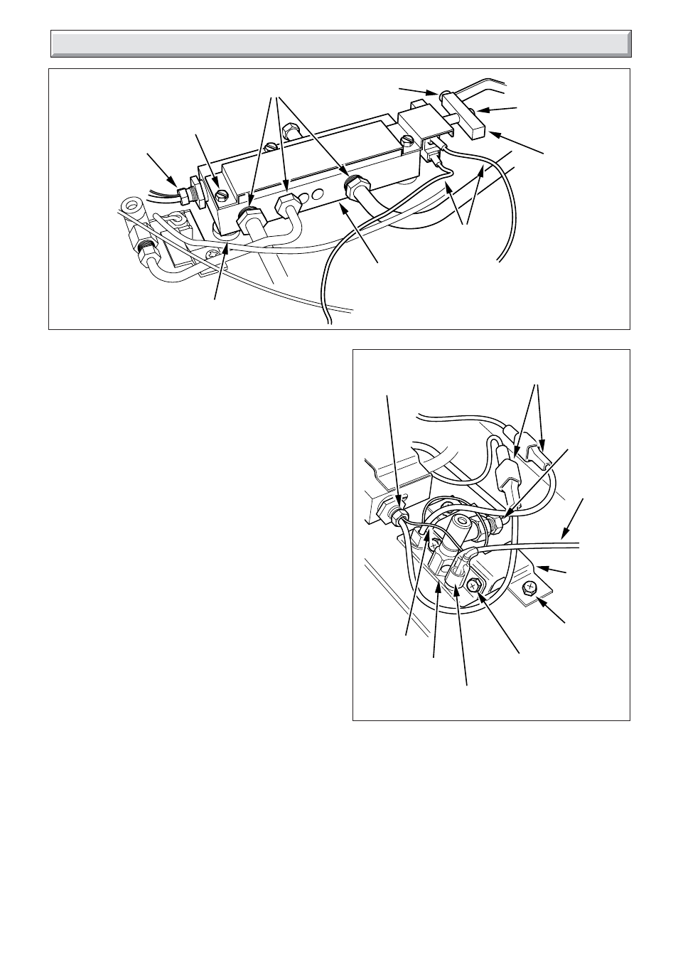
Diagram 8.3
6222
Diagram 8.4
THERMOCOUPLE
NUT
SECURING
SCREW (3)
UNION NUTS
SECURING
SCREW
SECURING
SCREW
GAS TAP
FITTING
BLOCK
ELECTRICAL
LEADS
GAS CONTROL
VALVE
SPACERS (3)
IGNITION
LEAD
THERMOCOUPLE
NUT
ELECTRICAL
CONNECTIONS
PILOT PIPE
UNION NUT
SECURING
SCREW (2)
SILICONE
COVER
SAFETY
DEVICE
CAPILLARY
SECURING
SCREW (2)
SAFETY
DEVICE
BRACKET
8.9 Gas Control Valve
Remove the fire front from the back boiler unit.
Follow instructions in Section 6.4 to remove the burner assembly
Remove the gas control valve, disconnecting the union nuts,
thermocouple nut, gas tap fitting block, electrical leads and gas
control valve securing screws, this will release the gas control
valve, see diagram 8.3.
Remove the microswitch 2, see relevant parts of Section 8.8.
When re-assembling make sure to refit the spacers between
the gas control valve and burner assembly.
8.10 Safety Device
Refer to Section 1.
Remove the fire front from the back boiler unit.
Follow instructions in Section 6.4 to remove the burner assembly
Refer to diagram 8.4, disconnect:
-the ignition lead
-the pilot pipe union at the safety device
-the thermocouple nut at the gas control valve
-the electrical connections
-the safety device bracket
-the safety device
8.11 Ignition Lead
Follow relevant parts of section 8.6.
Disconnect the ignition lead at the electrode and spark generator,
refer to diagrams 8.1 and 8.4.