3 installation – Glow-worm Chatsworth 4 User Manual
Page 11
11
221907C
3 Installation
10107
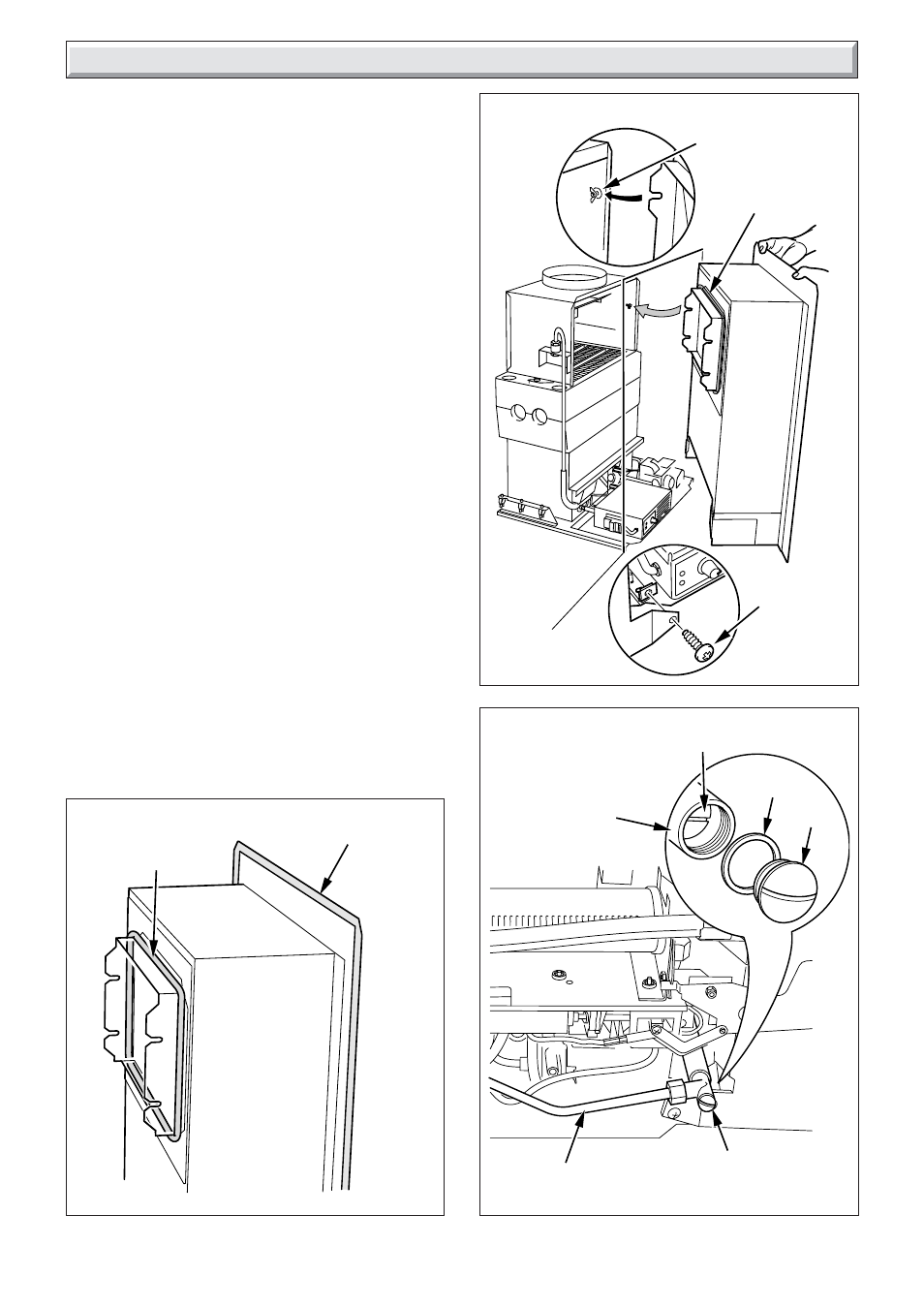
Diagram 3.2
10122
Diagram 3.3
GAS FIRE
SUPPLY COCK
WING NUT
AND PLAIN
WASHER (2)
SECURING
SCREW (2)
10104
Diagram 3.1
FIRE FRONT
FLUE SEAL
FIRE FRONT
FLUE SEAL
FIRE FRONT
WALL SEAL
3.1 Positioning the Fire Front
Note: Before fitting, make sure the wall surface to which the fire
front is to be fitted is vertical and flat. Any unevenness may
cause the whole assembly to become twisted or distorted when
fixing.
IMPORTANT. Ensure that the blanking plate, supplied with this
fire front, is fitted to the rear of the combustion chamber of the
back boiler unit before installing the fire front. Refer to the
installation and servicing instructions supplied with the back
boiler unit for fitting.
Fit the fire front flue seal supplied in the fittings pack around the
outside of the flue spigot, see diagram 3.1.
Fit the fire front wall seal, in three sections, supplied in the
fittings pack, first removing the backing strip, see diagram 3.1.
Place the fire front into the fire opening and make sure the flue
spigot fits into the draught diverter. Secure the fire front to the
back boiler assembly with two wing nuts plus plain washers and
the two securing screws provided, see diagram 3.2.
Fire Front Removal
This will be neccessary when servicing the back boiler unit.
Disconnect the union nut at the gas fire supply cock, see
diagram 3.3.
Remove the two securing screws, slacken the two wing nuts,
remove the fire front, see diagram 3.2.
IMPORTANT NOTE: Replace the fire front flue seal if neccessary.
Ensure the fire front flue seal is fitted before re-fitting the fire
front.
3.2 Gas Connection
Connect the gas supply tube, as diagram 3.3 tighten the nut at
the gas fire supply cock.
GAS SUPPLY
TUBE
GAS FIRE
SUPPLY
COCK
RESTRICTOR
SCREW
WASHER
CAP