4 lighting, testing and fitting of internal parts – Glow-worm Chatsworth 4 User Manual
Page 12
12
221907C
4 Lighting, Testing and Fitting of Internal Parts
5922
Diagram 4.1
5897
Diagram 4.2
CONTROL
KNOB
SECURING
SCREW (2)
SLIDER CONTROL
CONTROL
KNOB
OFF POSITION
COKE SETTING
HEAT SETTING 3
HEAT SETTING 2
HEAT SETTING 1
IGNITION POSITION
CONTROL
KNOB
SECURING
SCREW (2)
SLIDER CONTROL
Standard frame fitting
Wide frame fitting
LUBRICATE
HERE
SLIDER
Please ensure the “Benchmark” logbook (supplied with back
boiler unit) is completed and left with the user.
4.1 Lighting and Testing
The fire is fitted with a safety device.
The information in Section 1 must be observed.
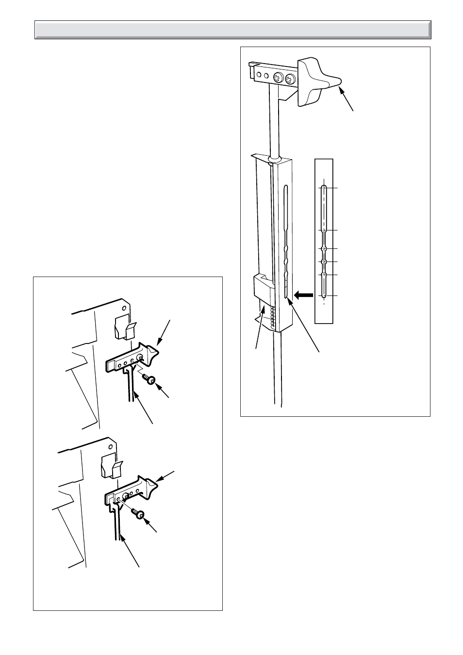
Fit knob to slider control, see diagram 4.1.
The slider control will move up and down, as it does the locator
selects positions from off to ignition, see diagram 4.2.
It may be necessary to lubricate the slider plunger with a
suitable grease, i.e. Rocol tap grease, Spec. M23600, if the
slider is stiff.
Make sure that the gas control assembly is in the OFF position,
that is, the slider control is at the top, see diagram 4.2.
Fit the battery, see diagram 4.3.
Remove the pressure test nipple screw and fit a suitable
pressure gauge, see diagram 4.4.
Turn the gas supply on at the gas fire supply cock by removing
cap and turning restrictor screw anti-clockwise, see diagram
3.3.
To check for gas soundness, apply leak detection fluid to all
joints.
WARNING. Take care when doing the following check, as the
burner has a naked flame.