6 servicing – Glow-worm Chatsworth 4 User Manual
Page 17
17
221907C
6224
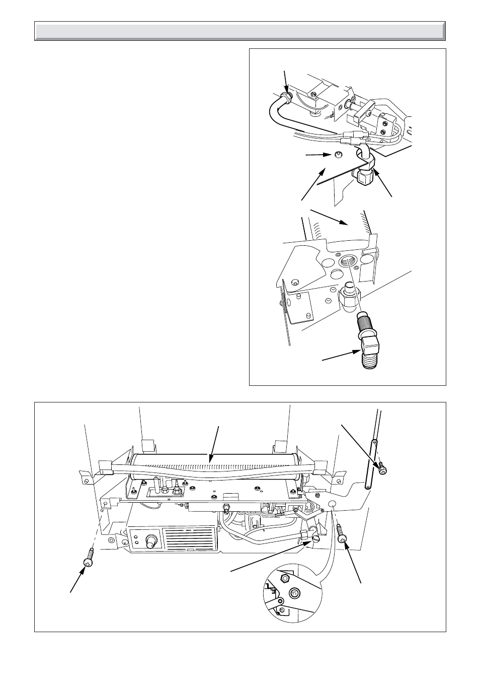
Diagram 6.2
GAS SUPPLY
PIPE UNION
NUT
BURNER
SECURING
SCREW (2)
INJECTOR
BURNER
ASSEMBLY
GAS CONTROL VALVE
CONNECTION
6 Servicing
9470
Diagram 6.1
BURNER
ASSEMBLY
BURNER ASSEMBLY
SECURING SCREW
BURNER ASSEMBLY
SECURING SCREW
SHOULDERED
SECURING SCREW
GAS FIRE
SUPPLY COCK
6.4 Burner and Injector
The burner can be cleaned, using a suitable soft brush or
vacuum cleaner.
Do not use a brush with wire bristles.
Disconnect the gas supply at the fire front gas service cock.
Remove the frame and fire front from the wall, refer to relevant
parts of Sections 4.3, 4.2, 3.2 and 3.1.
With the fire front removed lay it on its back. Remove the three
wires from the spark generator, see diagram 8.1.
Remove the shouldered securing screw, the burner securing
screws pull out the burner assembly, see diagram 6.1.
Disconnect the gas supply pipe union nut from the injector and
slacken the connection at the gas control valve, pull the pipe off
the injector, see diagram 6.2.
Remove the injector.
Do not clean the hole with a wire or sharp instrument.
6.5 Flue Blockage Safety Device
Refer to Section 1.1.
When cleaning make sure that all the holes in the safety device
are clear of dust and lint.
If damaged replace the safety device as Section 8.10.