ENMET EX-5000 User Manual
Page 9
MOS S/T
ENMET Corporation
7
3.1.2 Wiring
Run conduit and 16
AWG
wires to the enclosure from the power supply and controller. Since combustible gas may be
present, the S/T may be installed in a Class I Division 1 classified area as defined by the National Electrical Code, and
wiring must meet the provisions of that Code. All wires must pass through the seal fitting provided, and the fitting
must be potted after wiring is complete.
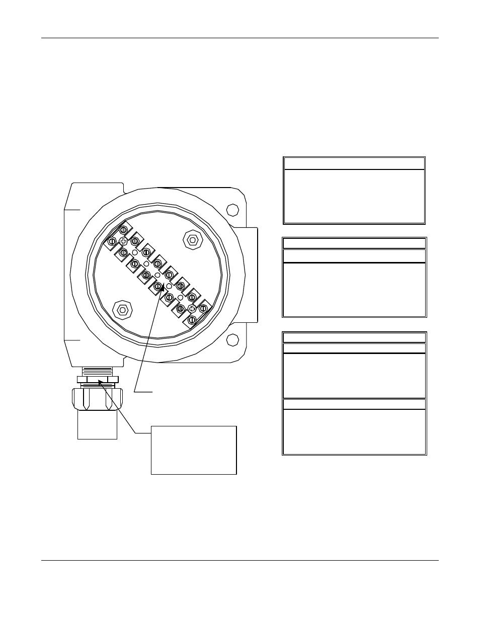
Open the enclosure, and remove the display from the circuit board by pulling it straight out. Release the two circuit
board retaining screws and remove the circuit board, exposing the terminal strip in the bottom of the enclosure. Do not
disconnect the circuit board wiring.
Connect the wires from the power supply and controller to the terminal strip TB1.
See figure 5 locations are as follows:
S/T Internal View with Circuit Board Removed
Figure 5: Terminal Strip Positions for MOS Sensor/Transmitter
See the instruction manual of the Controller being used with this S/T for the connection locations for these wires.
When using the S/T as a three wire device, use either ground as both power supply and loop ground.
After connecting the wires, replace the circuit board and the display; assure the LEDs are in the lenses. Replace
enclosure cover.
C
ONTROLLER
W
IRING
Position
Function
TB1-1
4 - 20 mA loop +
TB1-2
Loop ground
TB1-3
Power supply ground
TB1-4
+15 to 36 V
DC
power
For instruments serial # 777 and above
812 / 813 / 814 S
ENSOR
W
IRING
Position
Function
Wire Color
TB1-5
Heater
(Brown)
TB1-6
Signal
(Blue)
TB1-7
Ground
(Orange)
TB1-8
Not Used
For instruments serial # 776 and below
812 S
ENSOR
W
IRING
Position
Function
Wire Color
TB1-5
Heater
(Orange)
TB1-6
Signal
(Blue)
TB1-7
Ground
(Brown)
TB1-8
Not Used
813 / 814 S
ENSOR
W
IRING
Position
Function
Wire Color
TB1-5
Ground
(Brown)
TB1-6
Signal
(Blue)
TB1-7
Heater
(Orange)
TB1-8
Not Used
Terminal Strip TB1
1
2
3
4
5
6
7
8
Sensor Markings
812 is stamped 12
813 is stamped 13
814 is stamped 19