ENMET EX-5000 User Manual
Page 6
ENMET Corporation
Catalytic S/T
4
2.1.2 Wiring
Run conduit and 16
AWG
wires to the enclosure from the power supply and controller. Since combustible gas may be
present, the S/T may be installed in a Class I Division 1 classified area as defined by the National Electrical Code, and
wiring must meet the provisions of that Code. All wires must pass through the seal fitting provided, and the fitting
must be potted after wiring is complete.
Open the enclosure, and remove the display from the circuit board by pulling it straight out. Release the two circuit
board retaining screws and remove the circuit board, exposing the terminal strip in the bottom of the enclosure. Do not
disconnect the circuit board wiring.
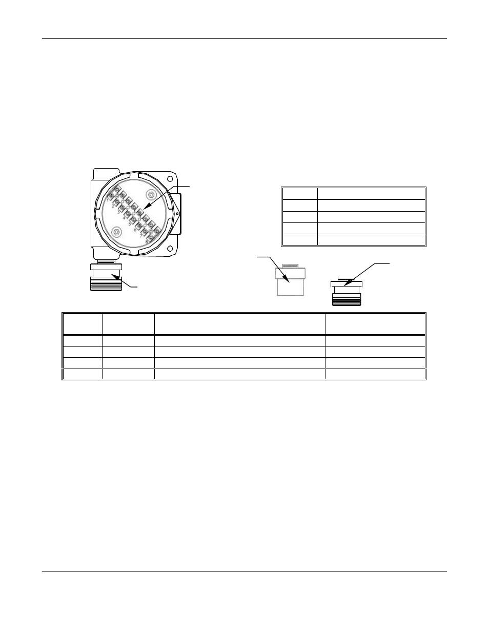
Connect the wires from the power supply and controller to the terminal strip. See figure 2 locations are as follows:
Internal View of S/T Terminal Strip
S
ENSOR
W
IRING
Position
Function
Wire Color for Sensor
(
external
threads) 03070-001 (
internal
threads
)
Wire Color for Sensor
03070-003
5
Compensator
Red
or
Black
Red
6
Output
Yellow
or
Red
White
7
Detector
Blue
or
White
Black
8
Not Used
Figure 2: Terminal Strip Positions for Catalytic Combustible Gas Sensor/Transmitter
When using the S/T as a three wire device, use either ground as both power supply and loop ground.
After connecting the wires, replace the circuit board and the display, assure the LEDs are in the lenses. Replace the
enclosure cover.
See the instruction manual of the Controller being used with this S/T for the connection locations for these wires.
2.2 Calibration
Wait 24 hours after initially supplying power to the sensor/ transmitter(S/T) before initial calibration. The S/T has been
precalibrated at the factory, and initial field calibration should result in only fine tuning to circuit, as well as a way to
check that installation is successful. It is not necessary to open the enclosure to make adjustment; the span and zero
potentiometers are operated with magnets from outside the enclosure.
C
AUTION
:
Do not open in classified area.
Do Not Adjust The Span Potentiometer Without Calibration Gas Applied to The Sensor; if this is done, the S/T is
rendered uncalibrated and incorrect. Magnetic switches control the span and zero potentiometers. The switch
locations are indicated by “+ and – Span” and “+ and – Zero” on the display panel per Figure 3; “+” increases the
value and “–” decreases it. Incremental changes in span and zero can be obtained by momentarily putting the end of
the magnet in proximity to the switch and then removing it; when the magnet is held in proximity to the switch and not
removed, the switch indexes continuously to the end of its range.
C
ONTROLLER
W
IRING
Position
Function
1.
4 - 20 mA loop +
2.
Loop ground
3.
Power supply ground
4.
+15 to 36 V
DC
power
Terminal Strip
Sensor 03070-003
External Threads
Sensor 03070-001
External Threads
Sensor 03070-001
Internal Threads