ENMET EX-5000 User Manual
Page 4
ENMET Corporation
Catalytic S/T
2
1.2 Features of Sensor / Transmitter
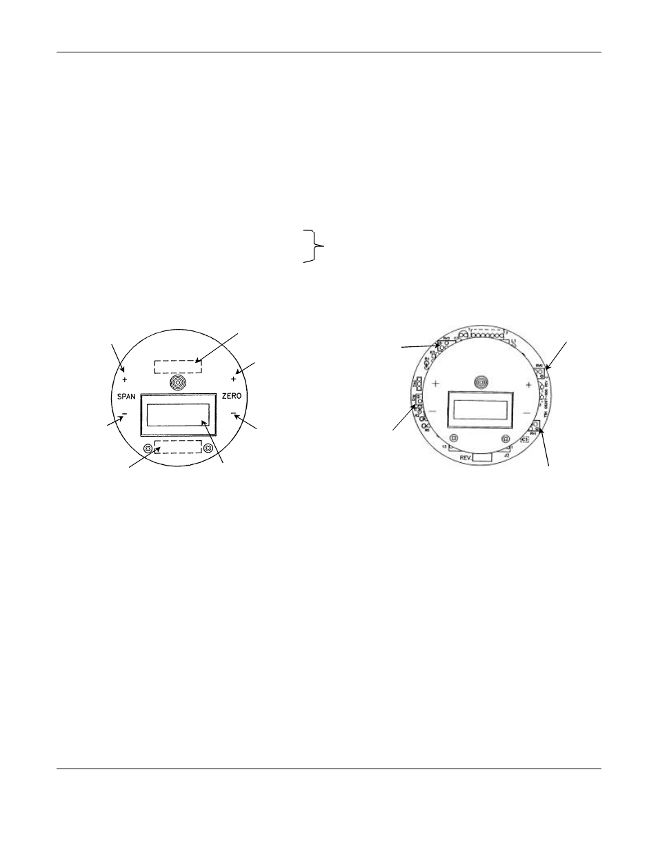
1.2.1 Magnetic Switches and Potentiometers
Magnetic switches control the span and purge potentiometer; a magnetic field pulse is applied by momentarily putting
the end of the magnet in proximity to the switch and then removing it. Since the magnetic field penetrates the
window, the enclosure cover is not removed in order to perform calibration.
The switch locations are indicated by “+ and –”. “+” increases the value and “–” decreases it. Incremental changes in
span can be obtained by momentarily putting the end of the magnet in proximity to the switch and then removing it; when
the magnet is held in proximity to the switch and not removed, the switch indexes continuously to the end of its range.
See figure 1a,
Locations of Typical Indicators and Controls on Display Plate for the locations of the following magnetic switches
+
Span increase
For increasing span.
–
Span decrease
For decreasing span.
N
OTE
: Do not adjust these unless calibration
gas is applied to the sensor.
P
Purge
When the purge option is present. For cleaning of a contaminated sensor, the
heater voltage is increased up to 20% by activating the purge switch for a short
time. There is an associated yellow LED, indicating when purge is activated.
Locations of Typical Indicators
and Controls on Display Plate
Potentiometer Locations
Figure 1a: Features of Sensor/Transmitter
See figure 1a, Potentiometer Locations for the locations of the following manual potentiometers on the S/T circuit board:
RV0
Zero
For zeroing of the display in clean air. Refer to calibration procedure, section 3.2 use this
potentiometer before applying calibration gas.
RV1
Heater
For adjusting the heater voltage of MOS sensors. Do not reset this potentiometer unless
advised by ENMET personnel.
RV2
Alarm
For setting the point at which the red LED on the S/ T face plate is illuminated. Use the
zero potentiometer to set the display at the alarm point value desired, then use this
potentiometer to set the LED to turn on at this point. Then return the display to zero. The
factory default setting is the high alarm set point.
RV3
Span
For manually setting the span. Do not reset this potentiometer unless advised by ENMET
personnel.
C
AUTION
:
Area must be declassified before removing cover to access these potentiometers.
Span
Potentiometer
Alarm
Potentiometer
ZERO
Potentiometer
Heater Potentiometer
C
AUTION
: This POT is factory set;
resetting may damage sensor
Increase Span
using Magnet
Decrease Zero
using Magnet
Decrease Span
using Magnet
Display
Increase Zero
using Magnet
Label: Alarm Point
and Gas
Label: Range