Figure 4: armored cable gland installation, Area must be declassified during installation, Ex-6100 – ENMET EX-6100 Series User Manual
Page 7: Enmet corporation
EX-6100
ENMET Corporation
4
Important
Connect enclosure
earth-ground to a high
integrity earth ground
ATEX certified Ex d armoured
cable glands
- +
PSU
- +
Aout
0
V
R
x
T
x
RS232
Conduit
or Shielded Cable
Conduit
or Armoured Cable
Mount vertically
as shown
N
/O
C
O
M
N
/C
Relay 1
Alarm 1
N
/O
C
O
M
N
/C
Relay 2
Alarm 2
N
/O
C
O
M
N
/C
Relay 3
Fault
3.2 Wiring the EX-6100 to a Control Unit
C
AUTION
:
Area must be declassified during installation.
If the
EX-6100
is installed in a hazardous location as defined by the National Electrical Code, then ALL wiring must be in
accordance with the National code and any local governing codes.
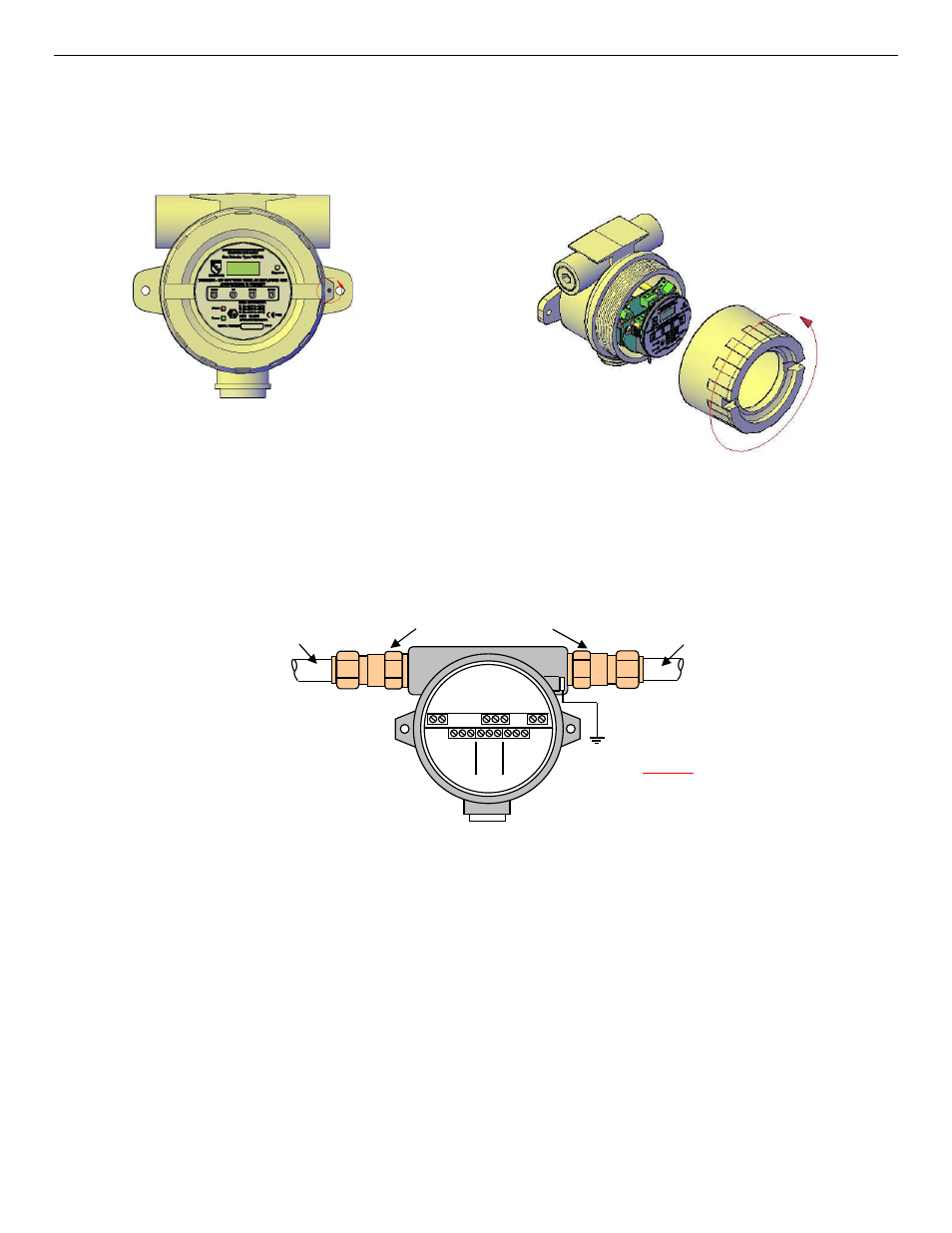
Open the enclosure, and remove the 2 screws that retain the display overlay to the circuit board.
Turn cover securing stud counter-clockwise to allow cover to open.
Remove cover by rotating counter-clockwise.
Figure3: Access to EX-6100 for Connection to a Control Unit
The cable entry threads are 20mm, ½” or ¾” NPT female.
The
EX-6100
enclosure is manufactured from die cast aluminum*. Therefore, the use of glands, conduit fittings and blanks
made from brass should be avoided because if moisture is present, bi-metallic corrosion may occur due to the chemical reaction
between the two materials.
Glands and fittings plated with nickel, tin or zinc will provide improved protection but in harsh environments the use of
stainless steel is recommended.
Figure 4: Armored Cable Gland Installation
Relays
- three relays are provided:
Alarm 1 and Alarm 2 are associated with the alarm points.
Alarm 3 is associated with fault conditions.
All relays are factory set to de-energize state non alarm.