Figure 3a: typical channel board, Caution, Table 4: potentiometers per channel – ENMET MX-48 User Manual
Page 11
MX48 C
ONTROL
ENMET Corporation
7
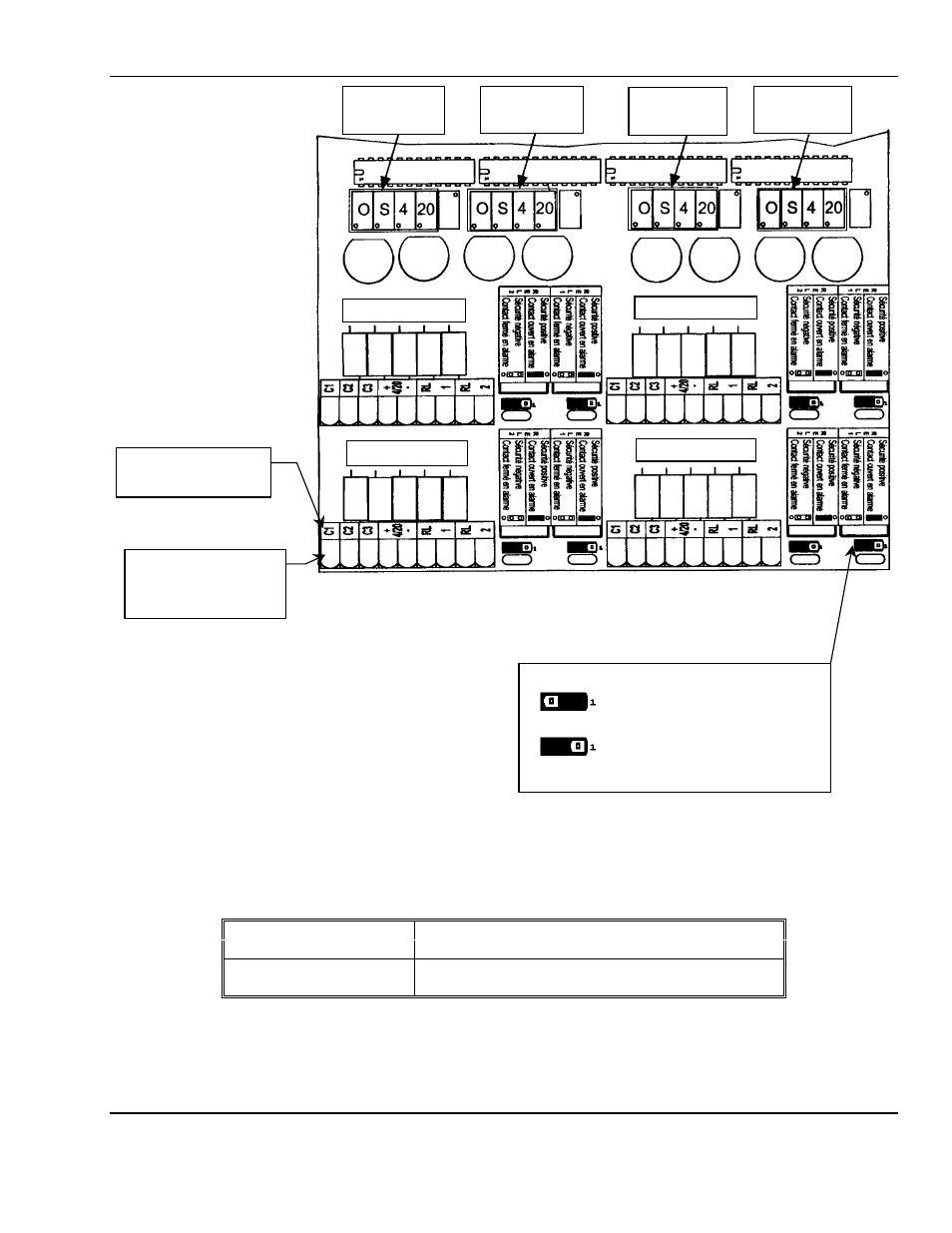
Figure 3a: Typical Channel Board
See Figure 1 for location of Channel Boards within
MX48 C
ONTROL
enclosure.
For channels 5 through 8 on second Channel Board:
♦
Channel 1 = Channel 5
♦
Channel 2 = Channel 6
♦
Channel 3 = Channel 7
♦
Channel 4 = Channel 8
Display Potentiometers
Caution:
Each channel display is adjusted at the factory and should not need to be readjusted. Any alignment
should be adjusted at the sensor/transmitter. Table 4 provides the function of
MX48 C
ONTROL
potentiometers if adjusted by mistake.
Table 4: Potentiometers per Channel
Left /2
O =
Control display
ZERO
potentiometer
S =
Control display span potentiometer
Right /2
4 =
potentiometer 4 mA / current output
20 =
potentiometer 20 mA / current output (for full scale)
Fuse
Fuse
Fuse
Fuse
Fuse
Display POTs for
Channel 1 or 5
see Caution
Channel 3 or 7
Channel 4 or 8
Channel 2 or 6
Display POTs for
Channel 2 or 6
see Caution
Display POTs for
Channel 3 or 7
see Caution
Display POTs for
Channel 4 or 8
see Caution
Fuse
Fuse
Fuse
Channel 1 or 5
1
2
3
4
5
9
6
8
7
Channel Terminal
Numbers used as
reference in Table 3
Channel Terminal
Typical Labeling
Channel Alarm Relays Jumper Positions
Jumper position on pins 1 & 2
for NC contact (factory setting)
Jumper position on pins 2 & 3
for NO contact