ENMET MX-48 User Manual
Page 10
ENMET Corporation
MX48 C
ONTROL
6
W
ARNING
:
Each channel of the
MX48 C
ONTROL
has a terminal strip to which all wiring for that channel is
connected. A typical four-channel circuit board is shown in Figure 3a and wiring for this terminal is
shown in Table 3.
3.2.3 4-20 Sensor/Transmitter
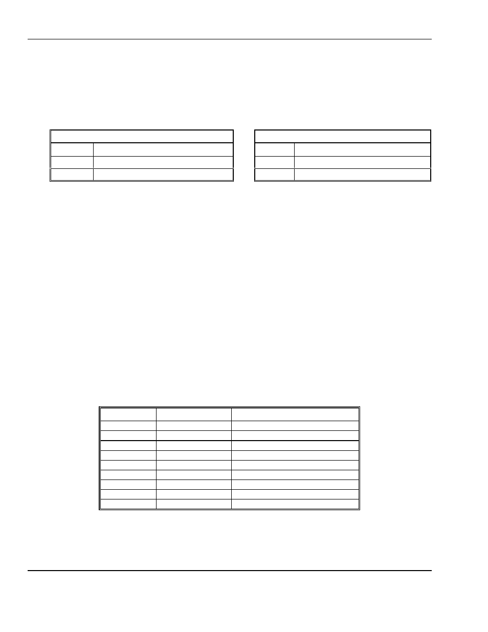
Sensor/Transmitters are connected to positions C1, C2 and C3 on each channel terminal strip. Connections are shown
in Table 1 for two wire S/T and Table 2 for three wire S/T. See Figure 3a for location of channel terminal strips.
Table 1: Wiring for a Two Wire S/T
Table 2: Wiring for a Three Wire S/T
Two Wire Sensor/Transmitter
Three wire Sensor/Transmitter
C1
Signal minus (–
–
–
–)
C1
Signal
C2
Not used
C2
Ground
C3
Signal plus, +24
V
DC
power
C3
+24
V
DC
power
4-20mA Output Signal
The (+ 4/20 -) positions in each channel terminal is the 4-20mA output from the Control. The plus and minus sides of
the loop are indicated on the terminal strip. See Figure 3a and Table 3.
3.2.4 Relay Contacts
Auxiliary alarms should be powered from an independent power source separate form the instrument power to avoid
alarm failure due to controller malfunction.
MX48 C
ONTROL
relay contacts for the first two alarm levels are on the
RL, 1, RL and 2
(reference # 6 – 9) positions
of each channel terminal strip, as indicated in Figure 3a and Table 3. There are 3-pin headers located to the right of the
channel terminals for setting relays to normally open or normally closed operation. To set relays place jumpers in the
position indicated in Figure 3a. These relays have a maximum capacity of 2 Amp at 230 Volts, and are programmed
as described in Section 5.
The system alarm relay contacts AL3 are on the power supply board, as shown in Figure 3.
3.2.5 Wiring Requirements
Sensor/Transmitters:
Wiring to the Sensor/Transmitters should be by two or three wire shielded cable. The
recommended cable is 18 gauge three wire,
ENMET
part number 66017-006, Alpha-1747C or
equivalent.
Output Loop:
Wiring to output loop should be similar two wire shielded cable.
Relay:
Relay wiring can be suitable insulated wire.
Table 3: Typical Channel terminal strip connections
Reference: #
Labeled
Connection
1
C1
Signal
2
C2
Ground
3
C3
+24
V
DC
4
+
+4-20mA output
5
–
–4-20mA output (Ground)
6
RL
Alarm 1 relay
7
1
Alarm 1 relay
8
RL
Alarm 2 relay
9
2
Alarm 2 relay