2 changing components, Figure 4: spectrum sp series sensor location – ENMET SPECTRUM SP User Manual
Page 12
SPECTRUM SP Series
ENMET Corporation
10
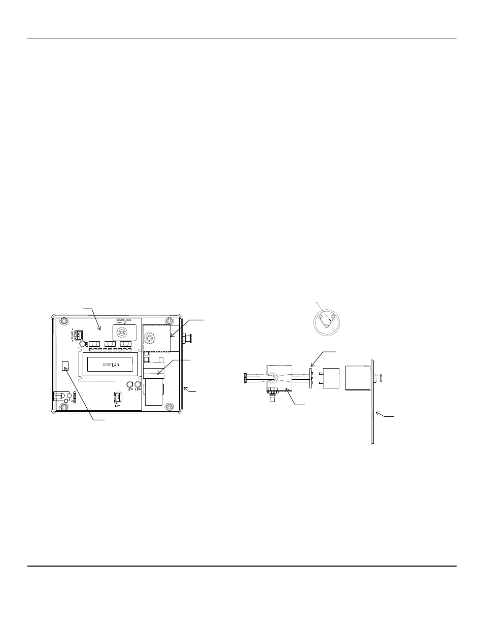
3.2 Changing Components
Changing the battery, the sensor, or the display requires that the back cover of the instrument to be removed; remove the four
phillips head screws and then the back cover. See Figure 5.
3.2.1 Sensor Removal and Replacement
A sensor must be replaced when it no longer responds adequately to the target gas. This is indicated by a low gas concentration
reading when exposed to a known concentration of the target gas, and the inability to calibrate the instrument, with a "C-
FAULT" display after calibration. Expected sensor lifetimes in normal environments are given in Table 1 Appendix A.
After removing the cover lift the pump from it’s retaining clip, along with the enclosure end cap.
Remove the sealing tape from the sensor chamber and remove the chamber cover.
Pull out the sensor and disconnect the sensor from the sensor circuit board. See Figure 4.
C
AUTION
:
New sensors may come with a shorting clip or spring that must be removed for proper operation.
Remove the shorting clip (if present) from the new sensor and plug the new sensor in the sensor circuit board.
Replace the sensor chamber cover and *sealing tape. *A quality electrical tape is adequate for this.
Replace pump in retaining clip.
Allow the sensor to stabilize in the instrument with the power on for one hour before recalibrating.
Follow the procedure for calibrating the instrument as outlined in Section 3.1.3 of this manual with the following
modification.
During the application of the span gas, the counter counts down from an upper value given in Table 2 Appendix A.
When the counter gets down to 60, adjust the calibration potentiometer located next to the display on the instrument PC
board, so that the display to the right of the counter reads a little above the calibration voltage given for the target gas in
Table 2 Appendix A. As the counter continues, turn the pot so that the calibration voltage is reached when the counter
reaches 30. This is a one-time adjustment to align the sensor output with the instrument electronics. It should only be
performed upon sensor replacement. All future calibrations should follow the procedure in Section 3.1.3.
Figure 4: SPECTRUM SP Series Sensor Location
Remove & Discard Clip/Spring
from Sensor
Bottom View of Sensor
Sensor Chamber with End Cap
S
e
n
s
o
r
Sensor Circuit Board
End Cap
Sensor
Chamber Cover
Internal View- Cover Removed
Sensor Chamber
And Sealing Tape
Pump
Circuit Board
End Cap
Calibration POT