Figure i, Figure e, Figure j – Elenco Digital Mulitmeter Kit User Manual
Page 7: Figure f, Figure g figure h
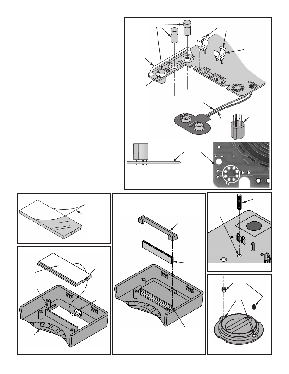
Figure I
Spring
Solder pad
on PC board
-6-
Close-up view of the
transistor socket and
PC board.
Solder Side
Figure E
Tab
Input Sockets
Shunt Wire
Red Wire
Black Wire
Solder
Battery Snap
Transistor
Socket
Fuse Clips
r
Remove the clear protective film from the
front of the LCD as shown in Figure F.
(Note: DO NOT remove the white backing
on the other side of the LCD).
r
Insert the LCD into the case (the tab on
the LCD must be in the same direction
shown in Figure G). Be sure to insert the
LCD under the tab on the case as shown
and push the edge of the LCD against the
raised area on the case. Press into place.
r
Place the zebra onto the grooved surface
of the LCD as shown in Figure H. Carefully
place the zebra clip around the zebra and
the raised area on the case.
r
Solder the spring to the solder pad on the
the legend side of the PC board as shown
in Figure I.
r
Cut open the plastic envelope containing
the grease and put a small amount of
grease in each spring hole of the selector
knob as shown in Figure J. Then, insert a
1/4” spring into each hole as shown in the
figure.
Clear
Protective Film
Figure J
Spring Holes
1/4” Springs
Figure F
LCD
Tab
Top Case
Tab
Zebra
Zebra Clip
Figure G
Figure H
Raised Area
on Case
Raised Area
on Case