Dc voltage measurement, Ac voltage measurement, Current measurement – Elenco Digital Mulitmeter Kit User Manual
Page 15: Figure 4, Figure 5, Figure 6
-14-
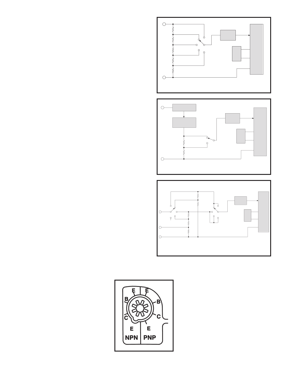
DC VOLTAGE MEASUREMENT
Figure 4 shows a simplified diagram of the DC voltage
measurement function. The input voltage divider resistors
add up to 1 megaohm. Each step down divides the voltage
by a factor of ten. The divider output must be within the
range –0.199 to +0.199 volts or the overload indicator will
function. The overload indication consists of a 1 in the most
significant digit and blanks in the remaining digits.
AC VOLTAGE MEASUREMENT
Figure 5 shows a simplified diagram of the AC voltage
measurement function. The AC voltage is first rectified and
passed through a low pass filter to smooth out the
waveform. A scaler reduces the voltage to the DC value
required to give the correct RMS reading.
CURRENT MEASUREMENT
Figure 6 shows a simplified diagram of the current
measurement function. Internal shunt resistors convert the
current to between –0.199 to +0.199 volts which is then
processed in the 7106 IC to light the appropriate LCD
segments. When current in the range of 10A is to be read,
it is fed to the 10A input and does not pass through the
selector switch.
Figure 4
Simplified DC Voltage Measurement Diagram
7106
100mV
REF
Low Pass
Filter
200mV
2V
1000V
200V
20V
900k
Ω
90k
Ω
100
Ω
900
Ω
9k
Ω
Volts
Common
Figure 5
Simplified AC Voltage Measurement Diagram
Volts
Common
7106
100mV
REF
Low Pass
Filter
Rectifier
Low Pass
Filter - Scaler
750V
200V
100
Ω
900
Ω
Figure 6
Simplified DC Amps Measurement Diagram
Common
10A
A
9
Ω
.99
Ω
.01
Ω
20mA
2mA
200
μ
A
200mA
10A
900
Ω
100
Ω
2mA
200
μ
A
20mA
200mA
10A
7106
100mV
REF
Low Pass
Filter