Ac volts test, Dc amps test, Dc volts test – Elenco Digital Mulitmeter Kit User Manual
Page 10: Figure o figure m figure n
AC VOLTS TEST
To test the ACV ranges, we will need a source of AC voltage. The AC power line is the most convenient.
CAUTION: Be very careful when working with 120VAC. Be sure that the range switch is in the 200 or 750VAC
position before connecting the test leads to 120VAC.
1) Set the range to 200VAC and measure the AC power line. The voltage should be about 120VAC. Compare
the reading to a meter of known accuracy.
2) Set the range to 750VAC and measure the AC power line. The voltage should be about 120VAC. Compare
the reading to a meter of known accuracy.
If either if the above tests fail:
a) Check the values and the soldering of resistors D3, R21 - R25, R34, R35.
b) Check that diode D3 is mounted as shown in the assembly instructions.
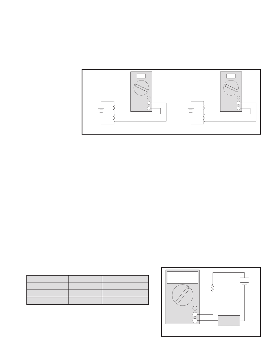
DC AMPS TEST
1) Set the range switch to 200
μ
A and connect the meter as in Figure O. With R
A
equal to 100k
Ω
the current
should be about 90
μ
A. Compare the reading to a known accurate meter.
2) Set the range switch and R
A
as in the following table. Read the currents shown and compare to a known
accurate meter.
If any of the above tests fail:
a) Check the fuse.
b) Check the value and soldering of resistors R8, R20, and R21.
DC VOLTS TEST
1) If you have a variable power supply, set the supply to about the midpoint of each of the DCV ranges and compare the
kit meter reading to a meter known accuracy.
2) If you do not have a variable power supply, make the following two tests:
a)
Set the range switch to 2V and measure the voltage across the 100
Ω
resistor of Figure M. You should get about
820mV. Compare the reading to a meter of known accuracy.
b)
Set the range switch to 200mV and measure the voltage across the 100
Ω
resistor of Figure N. You should get
about 90mV. Compare the reading to a meter of known accuracy.
If any of these tests fail:
a) Recheck the meter
calibration.
b) Check the value and the
soldering of resistors R2,
R20 - R27, R35, and
capacitor C3.
-9-
Figure O
Figure M
Figure N
1k
Ω
10A DC
V
Ω
mA
COM
100
Ω
9V
123
10k
Ω
10A DC
V
Ω
mA
COM
100
Ω
9V
123
Range Switch
R
A
Current (approx.)
2mA
10k
Ω
900
μ
A
20mA
1k
Ω
9mA
200mA
470
Ω
19mA
V
Ω
mA
COM
10A DC
123
Accurate
Meter
R
A
9V