Assembly instructions – Elenco Digital Mulitmeter Kit User Manual
Page 5
-4-
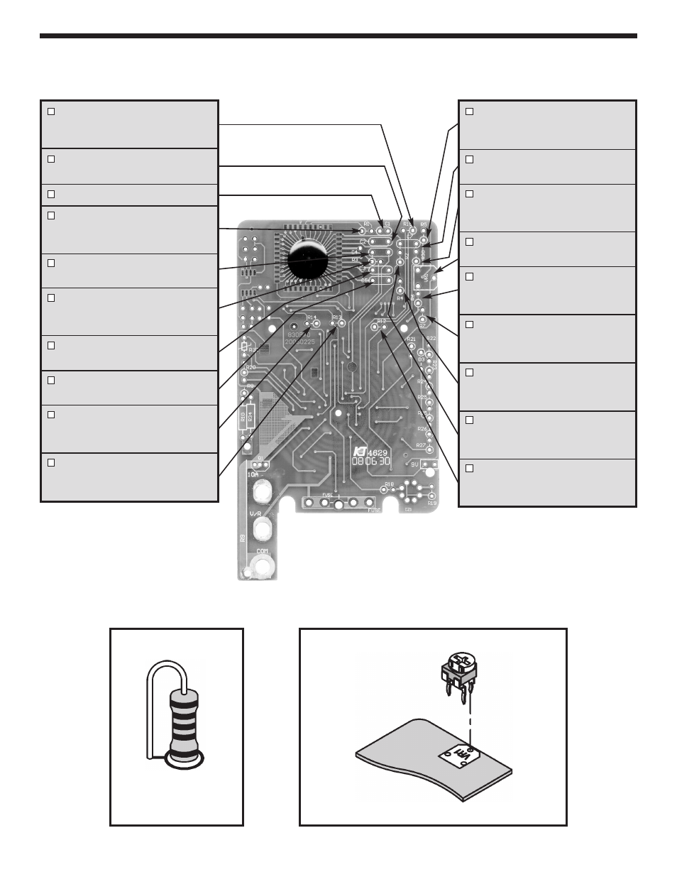
ASSEMBLY INSTRUCTIONS
Identify and install the following parts as shown. After soldering each part, mark a check
þ
in the box provided.
Be sure that solder has not bridged to an adjacent pad.
Figure B
Figure A
Stand resistor on end as
shown. Solder and cut
off the excess leads.
R15 - 220k
Ω
5% 1/4W Resistor
(red-red-yellow-gold)
(see Figure A)
C2 - .1
μ
F (104) Mylar Cap.
(small yellow)
C1 - 100pF (101) Discap
R1 - 150k
Ω
5% 1/4W Resistor
(brown-green-yellow-gold)
(see Figure A)
C4 - .1
μ
F (104) Mylar Capacitor
(small yellow)
R3 - 1M
Ω
5% 1/4W Resistor
(brown-black-green-gold)
(see Figure A)
C3 - .1
μ
F (104) Mylar Capacitor
(small yellow)
C5 - .1
μ
F (104) Mylar Capacitor
(small yellow)
R14 - 220k
Ω
5% 1/4W Resistor
(red-red-yellow-gold)
(see Figure A)
R13 - 220k
Ω
5% 1/4W Resistor
(red-red-yellow-gold)
(see Figure A)
Mount the potentiometer to the PC board as shown.
R5 - 1k
Ω
5% 1/4W Resistor
(brown-black-red-gold)
(see Figure A)
C7 - .1
μ
F 63V Mylar Cap.
(104 or 0.1)
R30 - 100k
Ω
5% 1/4W Resistor
(brown-black-yellow-gold)
(see Figure A)
VR1 - 220
Ω
(221) Potentiometer
(see Figure B)
R6 - 3k
Ω
1% 1/4W Resistor
(orange-black-black-brown-brown)
(see Figure A)
R7 - 30k
Ω
1% 1/4W Resistor
(orange-black-black-red-brown)
(see Figure A)
R4 - 100k
Ω
5% 1/4W Resistor
(brown-black-yellow-gold)
(see Figure A)
R2 - 470k
Ω
5% 1/4W Resistor
(yellow-violet-yellow-gold)
(see Figure A)
R12 - 220k
Ω
5% 1/4W Resistor
(red-red-yellow-gold)
(see Figure A)