Warning, Identifying resistor values, Parts identification – Elenco Digital Mulitmeter Kit User Manual
Page 3: Identifying capacitor values
-2-
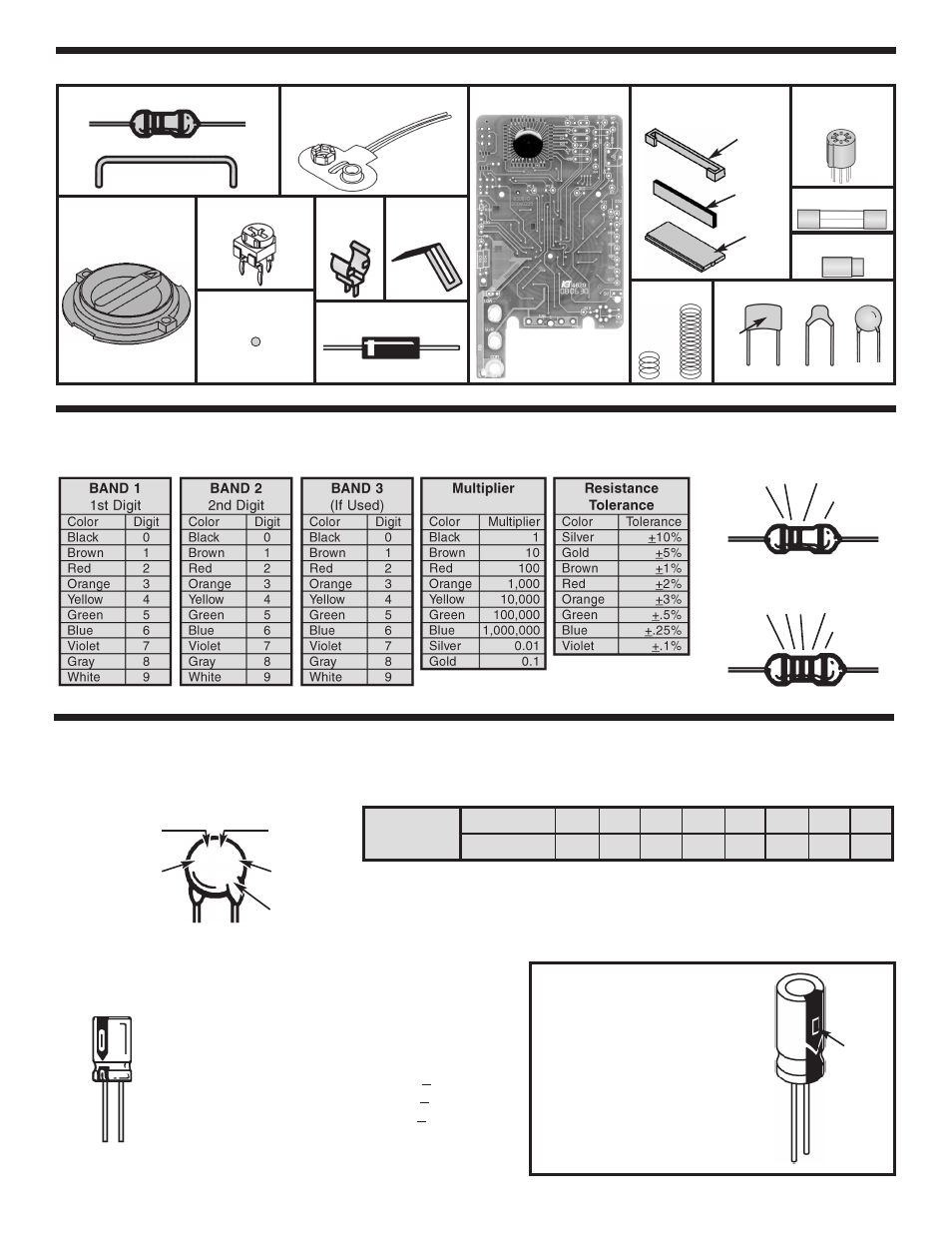
IDENTIFYING RESISTOR VALUES
Use the following information as a guide in properly identifying the value of resistors.
5 Bands
1
2
Multiplier
Tolerance
Resistors
PARTS IDENTIFICATION
PC Board with IC
Potentiometer
Ball Bearing
Selector Knob
Battery Snap
Fuse
Clip
Slide
Contact
Transistor
Socket
Fuse
Input Socket
3
4 Bands
1
2
Multiplier
Tolerance
Diode
Shunt Wire
LCD Assembly
Zebra Clip/Zebra/LCD
Capacitors
Discap
Mylar
C7
IDENTIFYING CAPACITOR VALUES
Capacitors will be identified by their capacitance value in pF (picofarads), nF (nanofarads), or
μ
F (microfarads). Most
capacitors will have their actual value printed on them. Some capacitors may have their value printed in the following
manner. The maximum operating voltage may also be printed on the capacitor.
Second Digit
First Digit
Multiplier
Tolerance*
For the No.
0
1
2
3
4
5
8
9
Multiply By
1
10
100
1k
10k 100k .01
0.1
Multiplier
Note: The letter “R” may be used at times to
signify a decimal point; as in 3R3 = 3.3
10
μ
F 16V
103K
100V
The letter M indicates a tolerance of +20%
The letter K indicates a tolerance of +10%
The letter J indicates a tolerance of +5%
Maximum Working Voltage
The value is 10 x 1,000 =
10,000pF or .01
μ
F 100V
*
Zebra
Clip
Zebra
LCD
Electrolytic capacitors have a positive and a
negative electrode. The negative lead is
indicated on the packaging by a stripe with
minus signs and possibly arrowheads.
Warning:
If the capacitor is
connected with incorrect
polarity, it may heat up
and either leak, or cause
the capacitor to explode.
Polarity
Marking
Springs