Figure f, Figure l, Figure i – Elenco Compact Digital Multimeter User Manual
Page 7: Figure k, Figure j, Figure g, Figure h
-6-
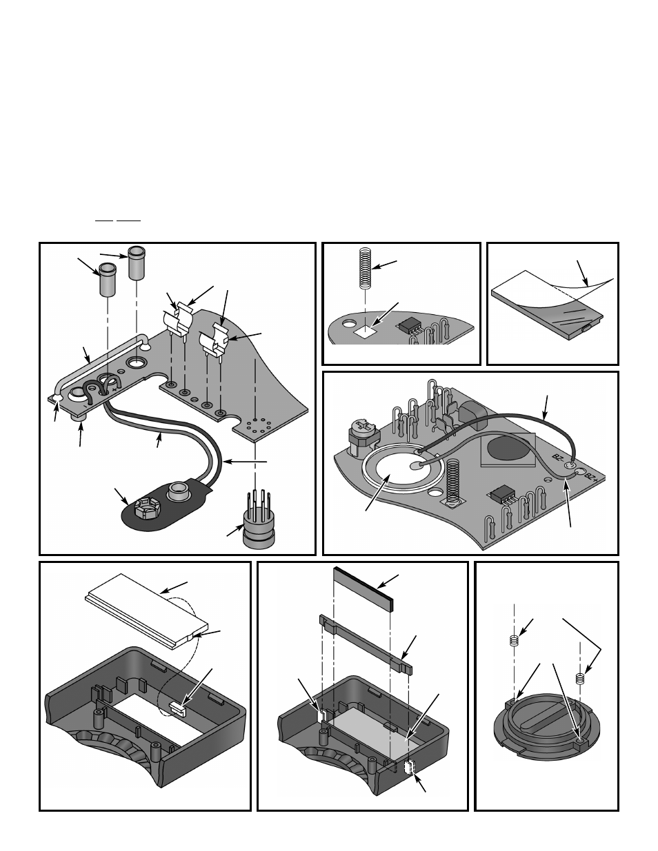
Figure F
Tab
Input sockets
Shunt wire
Red wire
Black wire
Solder
Battery snap
Transistor socket
Fuse clips
Clear protective film
Figure L
Spring holes
4mm Springs
Figure I
LCD
Zebra
Zebra frame
Figure K
Mounting
tabs
Tab
Figure J
Mounting tabs
LCD
Mounting tab
Figure G
Input socket
Tab
r Feed the battery snap wires up through the holes
in the PC board from the solder side as shown in
Figure F. Insert the red wire into the hole marked
(+) and black wire into hole marked (–) as shown.
Solder the wires to the PC board.
r Peel the backing off the foam tape on the buzzer
and attach it to the PC board as shown in Figure H.
r Solder the red wire to the BZ+ pad and black wire
to the BZ– pad as shown in Figure H.
r Remove the clear protective film from the front of
the LCD as shown in Figure I.
(Note: DO NOT remove the white backing on the
other side of the LCD).
r Insert the LCD into the frame (the tab on the LCD
must be in the same direction shown in Figure J).
r Insert the zebra frame as shown in Figure K.
r Place the zebra onto the grooved surface of the
LCD as shown in Figure K.
r Cut open the plastic envelope containing the
grease and put a small amount of grease in each
spring hole of the selector knob as shown in
Figure L. Then, insert a 4mm spring into each hole
as shown in the figure.
Figure H
Buzzer
Red wire (BZ+)
Black wire (BZ–)
11mm Spring
Solder pad
on PC board