Final assembly – Elenco Compact Digital Multimeter User Manual
Page 11
-10-
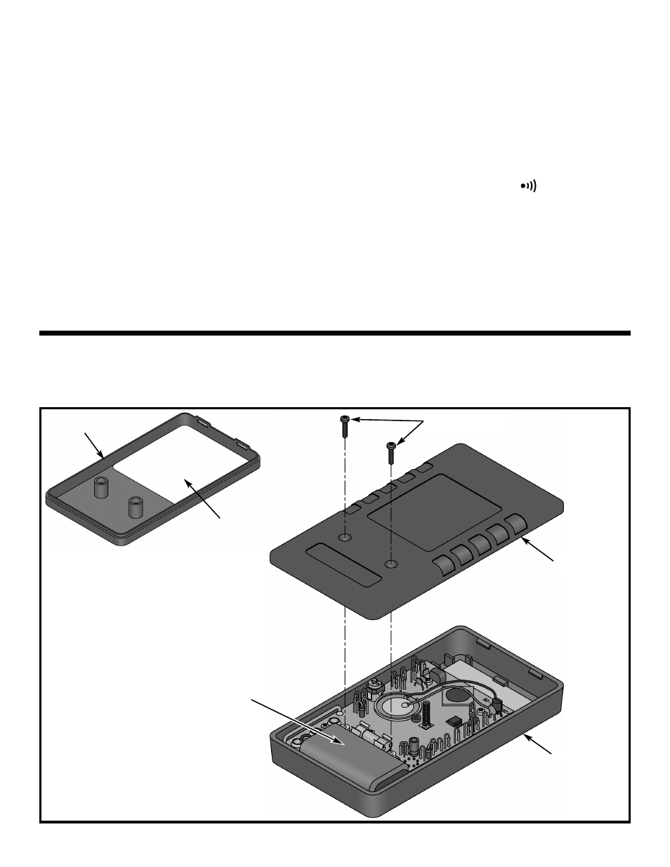
FINAL ASSEMBLY
r Peel the backing off of the shield label and stick it onto the case bottom in the location shown in Figure Ra.
r Snap the case bottom onto the case top and fasten with the two 10mm screws as shown in Figure R.
Case
bottom
10mm Screws
Case top
Figure R
Battery
Case bottom
Shield label
Figure Ra
RESISTANCE / DIODE TEST
1) Measure a resistor of about half of the full scale
value of each resistance range. Compare the kit
meter readings to those from a meter of known
accuracy.
2) Measure the voltage drop of a good silicon diode.
You should read about 700mV. Power diodes and
the base to emitter junction of power transistors
may read less.
If any of these tests fail:
a) Check the values and the soldering of
resistors PTC, R1-6, R9, and R16.
h
FE
TEST
1) Set the range switch to h
FE
and insert a small
transistor into the appropriate NPN or PNP holes
in the transistor socket.
2) Read the h
FE
of the transistor. The h
FE
of
transistors varies over a wide range, but you will
probably get a reading between 100 and 300.
If this check fails:
a) Check the value and soldering of resistors
R19-21.
CONTINUITY TEST
1) Set the range switch to the “ ” position.
2) Touch the tips together and all zeros displays as
the buzzer sounds.
If this check fails:
a) Check the value and soldering of resistors
R22-29, Q2, C7, and buzzer.