Dc voltage measurement, Ac voltage measurement, Current measurement – Elenco Compact Digital Multimeter User Manual
Page 15: Figure 4, Figure 5, Figure 6, Figure 7, Resistance measurement
-14-
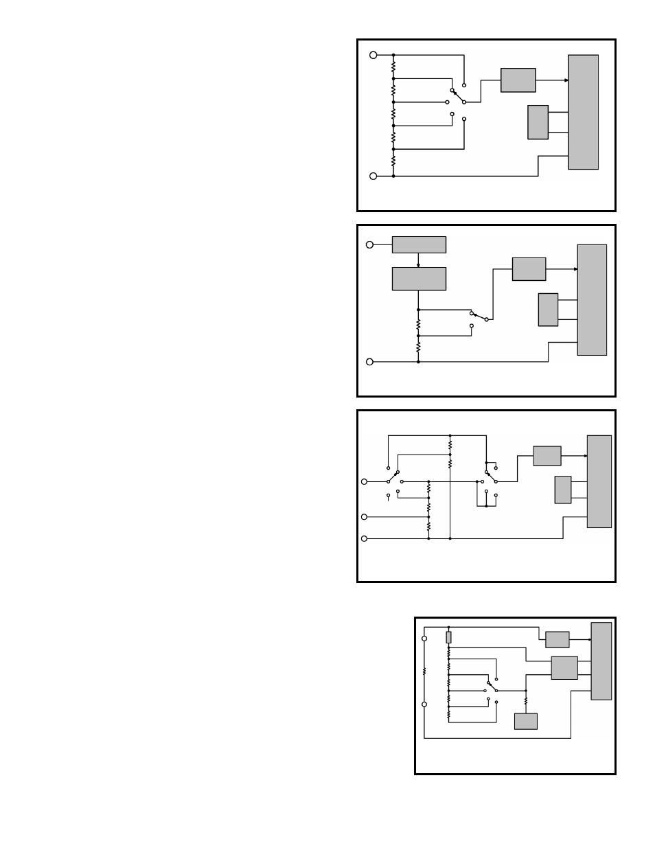
DC VOLTAGE MEASUREMENT
Figure 4 shows a simplified diagram of the DC voltage
measurement function. The input voltage divider resistors
add up to 1 megaohm. Each step down divides the voltage
by a factor of ten. The divider output must be within the
range –0.199 to +0.199 volts or the overload indicator will
function. The overload indication consists of a 1 in the most
significant digit and blanks in the remaining digits.
AC VOLTAGE MEASUREMENT
Figure 5 shows a simplified diagram of the AC voltage
measurement function. The AC voltage is first rectified and
passed through a low pass filter to smooth out the
waveform. A scaler reduces the voltage to the DC value
required to give the correct RMS reading.
CURRENT MEASUREMENT
Figure 6 shows a simplified diagram of the current
measurement function. Internal shunt resistors convert the
current to between –0.199 to +0.199 volts which is then
processed in the 7106 IC to light the appropriate LCD
segments. When current in the range of 10A is to be read,
it is fed to the 10A input and does not pass through the
selector switch.
Figure 4
Simplified DC Voltage Measurement Diagram
7106
100mV
REF
Low Pass
Filter
200mV
2V
600V
200V
20V
900k
Ω
90k
Ω
100
Ω
900
Ω
9k
Ω
Volts
Common
Figure 5
Simplified AC Voltage Measurement Diagram
Volts
Common
7106
100mV
REF
Low Pass
Filter
Rectifier
Low Pass
Filter - Scaler
600V
200V
100
Ω
900
Ω
Figure 6
Simplified DC Amps Measurement Diagram
Common
10A
A
9
Ω
.99
Ω
.01
Ω
20mA
2mA
200
μA
200mA
10A
900
Ω
100
Ω
2mA
200
μA
20mA
200mA
10A
7106
100mV
REF
Low Pass
Filter
Figure 7
Simplified Resistance Measurement Diagram
Ω
900k
Ω
Test
Resistor
100
Ω
900
Ω
2M
Ω/Dio
200
Ω
7106
Reference
Voltage
Low Pass
Filter
Voltage
Source
Common
90k
Ω
9k
Ω
2m
Ω
20k
Ω
200k
Ω
Fuse
RESISTANCE MEASUREMENT
Figure 7 shows a simplified diagram of the resistance measurement
function. A simple series circuit is formed by the voltage source, a
reference resistor from the voltage divider (selected by the selector
switches), and the test (unknown) resistor. The ratio of the two resistors
is equal to the ratio of their respective voltage drops. Therefore, since
the value of one resistor is known, the value of the second can be
determined by using the voltage drop across the known resistor as a
reference. This determination is made directly by the A/D converter.
Overall operation of the A/D converter during a resistance
measurement is basically as described earlier with one exception. The
reference voltage present during a voltage measurement is replaced by
the voltage drop across the reference resistor. This allows the voltage
across the unknown resistor to be read during the read period.