Specifications, Measurement, Figure 9 – Elenco Compact Digital Multimeter User Manual
Page 16: Continuity measurement, Figure 8, Figure 9 shows a simplified diagram of the h, Of the transistor
DIODE CHECK
RANGE
RESOLUTION
MAX TEST CURRENT
MAX OPEN CIRCUIT VOLTAGE
DIODE
1mV
1.4mA
2.8V
TRANSISTOR h
FE
TEST
RANGE
TEST RANGE
TEST CURRENT
TEST VOLTAGE
NPN/PNP
0 - 1000
Ib = 10
μA
Vce 3V
CONTINUITY TEST
Audible Indication: Less than 20
Ω approx.
-15-
SPECIFICATIONS
GENERAL
DISPLAY
3 1/2 digit LCD, with polarity
OVERRANGE INDICATION
3 least significant digits blanked.
MAXIMUM VOLTAGE BETWEEN
TERMINALS AND EARTH GROUND
CAT II 600V
STORAGE ENVIRONMENT
–10
O
C to 50
O
C.
TEMPERATURE COEFFICIENT
(0
O
C to 18
O
C and 28
O
C to 50
O
C)
less than 0.1 x applicable accuracy
specification per
O
C.
POWER
9V alkaline or carbon zinc battery.
FUSE
200mA/250V
DIMENSIONS
126 x 70 x 24mm.
DC VOLTAGE
RANGE
RESOLUTION
ACCURACY
200mV
0.1mV
+0.5% rdg + 2d
2000mV
1mV
+0.5% rdg + 2d
20V
10mV
+0.5% rdg + 2d
200V
100mV
+0.5% rdg + 2d
600V
1V
+0.5% rdg + 2d
MAXIMUM ALLOWABLE INPUT
250V rms for 200mV, 600VDC
or rms AC for other ranges.
INPUT IMPEDANCE
1M
Ω.
DC CURRENT
RANGE
RESOLUTION
ACCURACY
200
μA
0.1
μA
+1.8% rdg + 2d
2000
μA
1
μA
+1.8% rdg + 2d
20mA
10
μA
+1.8% rdg + 2d
200mA
100
μA
+2.5% rdg + 2d
10A
10mA
+3% rdg + 3d
OVERLOAD PROTECTION 200mA/250V fuse (
μA,mA input only).
10A not fused (15 seconds only)
AC VOLTAGE
RANGE
RESOLUTION
ACCURACY
200V
100mV
+2% rdg + 10d
600V
1V
+2% rdg + 10d
MAXIMUM ALLOWABLE INPUT
600VDC or rms AC.
FREQUENCY
45 - 450Hz.
RESISTANCE
RANGE
RESOLUTION
ACCURACY
200
Ω
0.1
Ω
+1% rdg + 10d
2000
Ω
1
Ω
+1% rdg + 10d
20k
Ω
10
Ω
+1% rdg + 10d
200k
Ω
100
Ω
+1% rdg + 10d
2000k
Ω
1k
Ω
+1% rdg + 4d
MAXIMUM OPEN CIRCUIT VOLTAGE
3.2V.
MAXIMUM ALLOWABLE INPUT
250V rms AC
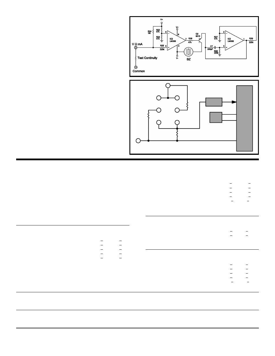
h
FE
MEASUREMENT
Figure 9 shows a simplified diagram of the h
FE
measurement function. Internal circuits in the
7106 IC maintain the COMMON line at 2.8 volts
below V+. When a PNP transistor is plugged into
the transistor socket, base to emitter current
flows through resistor R1. The voltage drop in
resistor R1 due to the collector current is fed to
the 7106 and indicates the h
FE
of the transistor.
For an NPN transistor, the emitter current
through R2 indicates the h
FE
of the transistor.
Figure 9
R1
Common
R3
R2
PNP
NPN
7106
100mV
Ref.
Low Pass
Filter
V+
E
C
C
E
B
B
CONTINUITY MEASUREMENT
Figure 8 shows a diagram of the continuity
measurement function. The circuit uses two op-
amps and a piezoelectric buzzer. When the
leads are connected across a circuit and the
resistance less than 20
Ω the circuit oscillates
and the buzzer sounds.
Figure 8