Assemble components to the pc board – Elenco Telephone Bug User Manual
Page 6
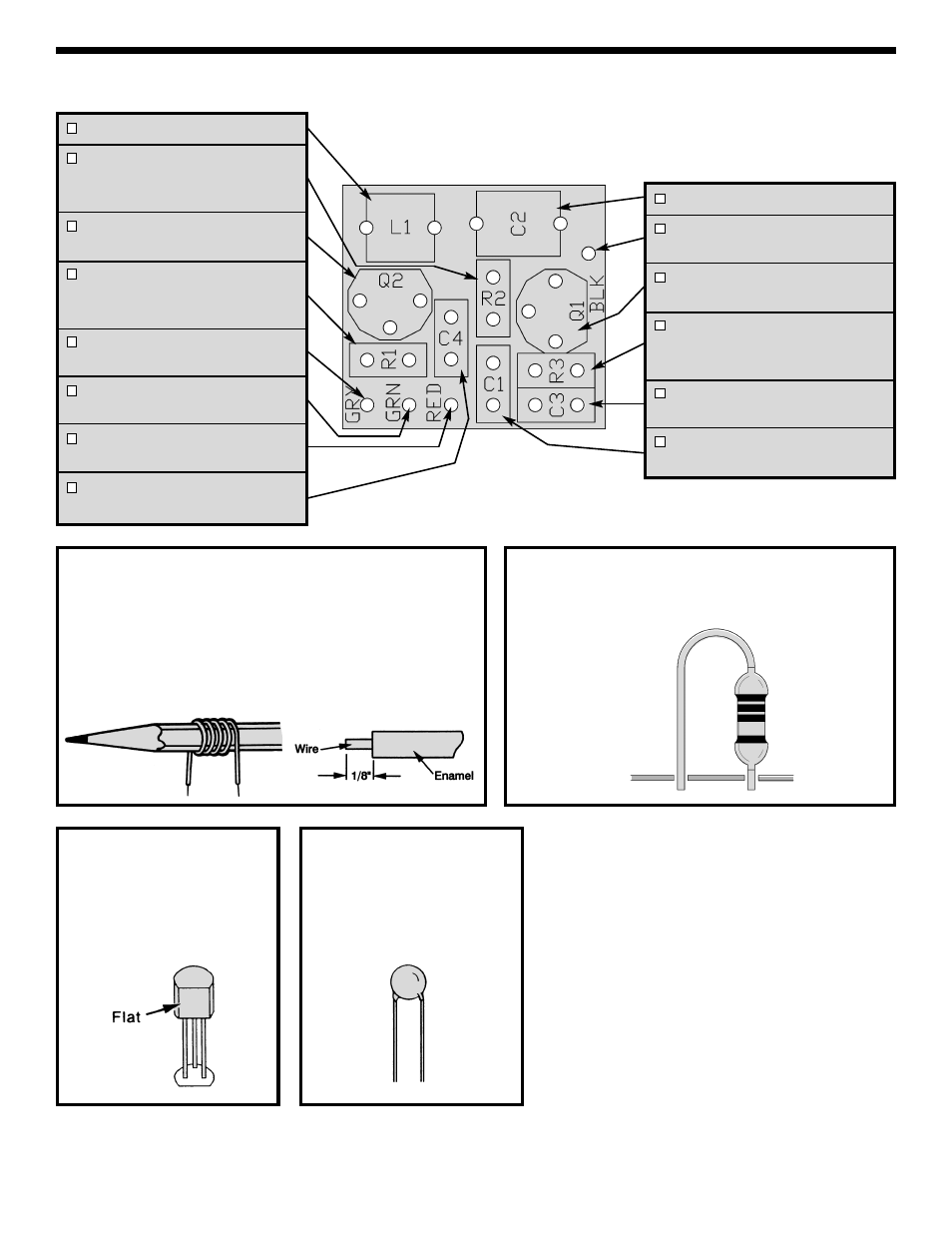
ASSEMBLE COMPONENTS TO THE PC BOARD
Figure A
Scrape off 1/8” of enamel off of both ends of the 6”
enamel wire. This will allow the wire to be soldered to the
PC board pads. Wind the enamel wire around a pencil. Be
sure to leave some straight wire at the ends of the coil so that
it can be mounted. Carefully slide the coil off of the pencil
and mount it in the place shown on the top legend. Solder in
place.
Figure B
Mount the resistors vertically to the PC board in the
places shown on the top legend. Solder and cut off
excess leads.
Figure C
Mount the transistors with the
flat side in the same direction
as shown on the PC board.
Solder and cut off the excess
leads.
Figure D
Mount the capacitor onto the
PC board as marked on the
PC board. Solder and cut off
the excess leads.
-5-
PC board shown at three
times the actual size.
L1 - Coil (see Figure A)
R2 - 270k
Ω 5% 1/4W Resistor
(red-violet-yellow-gold)
(see Figure B)
Q2 - MPSA56 Transistor
(see Figure C)
R1 - 47
Ω 5% 1/4W Resistor
(yellow-violet-black-gold)
(see Figure B)
GRY - Gray Wire (Strip 1/4” of
insulation off of both ends.)
GRN - Green Wire (Strip 1/4” of
insulation off of both ends.)
RED - Red Wire (Strip 1/4” of
insulation off of both ends.)
C4 - 470pF (471) Capacitor
(see Figure D)
C2 - 5-40pF Trimmer Cap
BLK - Black Wire (Strip 1/4” of
insulation off of one end.)
Q1 - 2N3904 Transistor
(see Figure C)
R3 - 680
Ω 5% 1/4W Resistor
(blue-gray-brown-gold)
(see Figure B)
C3 - 47pF (47) Capacitor
(see Figure D)
C1 - 100pF (101) Capacitor
(see Figure D)