103k, Important notice, Introduction – Elenco Telephone Bug User Manual
Page 3: Circuit operation, Identifying capacitor values, Identifying resistor values
IMPORTANT NOTICE
It is illegal to listen to a telephone conversation without the person’s consent. This kit is designed for educational
purposes only. It is meant to teach students and hobbyists the transmitting principle for a cordless telephone.
The manufacturer of this kit cannot be held responsible for any illegal use.
INTRODUCTION
The Telephone Bug is really a miniature FM radio transmitter broadcasting within the 88 to 108MHz (megahertz)
band. It is designed to be wired inside a telephone or the wires leading to the telephone. The voice frequencies
carried by the telephone wires modulate the FM transmitter allowing both sides of the telephone conversation
to be heard on any standard FM radio. Because of the unique circuitry , no battery is needed to operate the
unit. The power is taken from the telephone line.
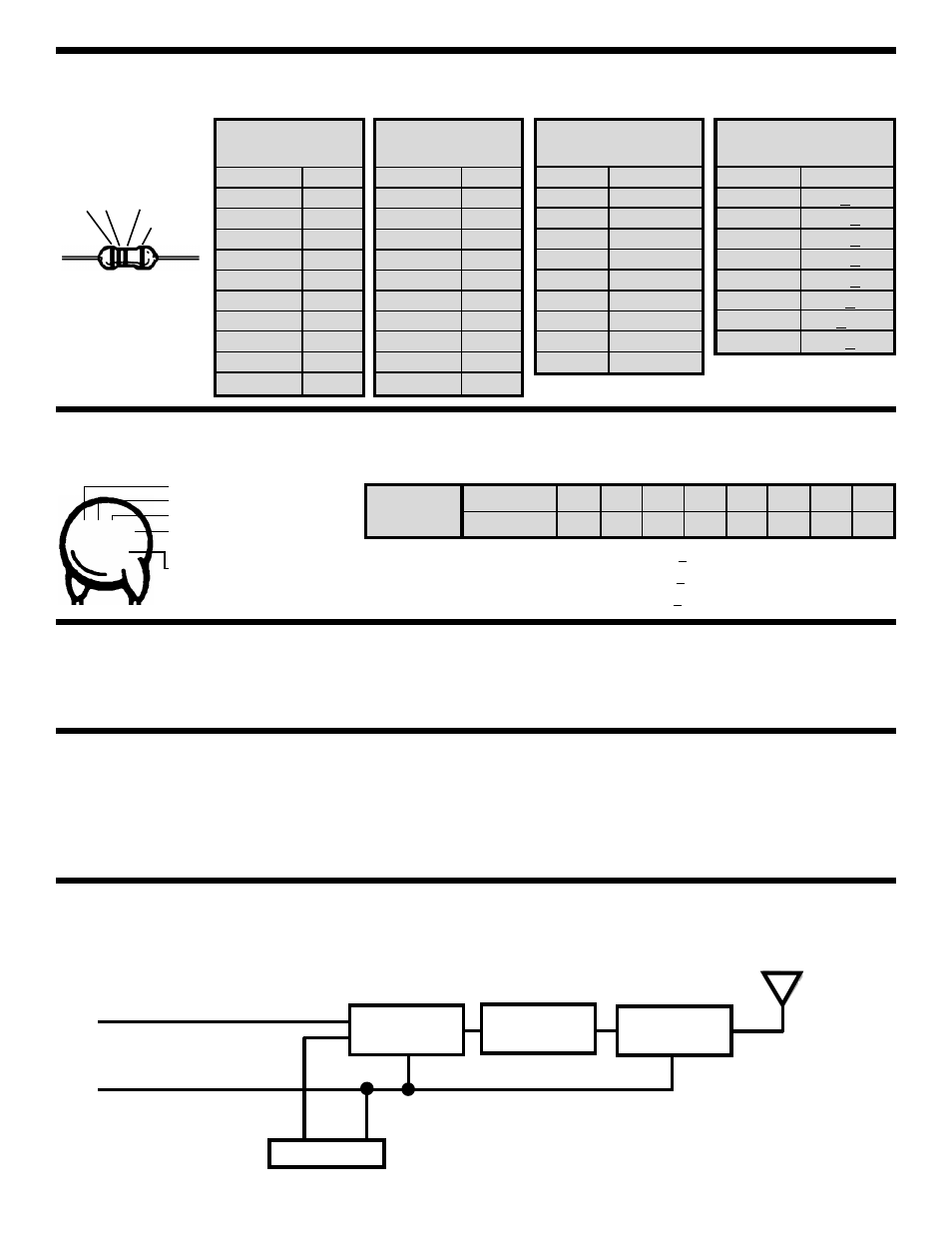
CIRCUIT OPERATION
Figure 1 is a block diagram of how the Telephone Bug works. It consists of an audio amplifier, modulator, an
RF oscillator and an antenna. We shall look at these basic circuits and examine how they function.
-2-
Audio
Amplifier
Modulator
RF
Oscillator
Antenna
Black Wire
Telephone
Gray Wire
Red Wire
Telephone Lines Input
Green Wire
IDENTIFYING CAPACITOR VALUES
Capacitors will be identified by their capacitance value in pF (picofarads), nF (nanofarads), or
μF (microfarads). Most capacitors will have
their actual value printed on them. Some capacitors may have their value printed in the following manner.
For the No.
0
1
2
3
4
5
8
9
Multiply By
1
10
100
1k
10k 100k .01
0.1
Multiplier
IDENTIFYING RESISTOR VALUES
Use the following information as a guide in properly identifying the value of resistors.
BAND 1
1st Digit
Color
Digit
Black
0
Brown
1
Red
2
Orange
3
Yellow
4
Green
5
Blue
6
Violet
7
Gray
8
White
9
BAND 2
2nd Digit
Color
Digit
Black
0
Brown
1
Red
2
Orange
3
Yellow
4
Green
5
Blue
6
Violet
7
Gray
8
White
9
Multiplier
Color
Multiplier
Black
1
Brown
10
Red
100
Orange
1,000
Yellow
10,000
Green
100,000
Blue
1,000,000
Silver
0.01
Gold
0.1
Resistance
Tolerance
Color
Tolerance
Silver
+10%
Gold
+5%
Brown
+1%
Red
+2%
Orange
+3%
Green
+.5%
Blue
+.25%
Violet
+.1%
Bands
1
2
Multiplier
Tolerance
Second Digit
First Digit
Multiplier
Tolerance
103K
100V
Maximum
Working Voltage
The value is 10 x 1,000 = 10,000pF or .01
μF 100V
The letter M indicates a tolerance of +20%
The letter K indicates a tolerance of +10%
The letter J indicates a tolerance of +5%
Note:
The letter “R” may
be used at times to
signify a decimal point; as
in 3R3 = 3.3