The modulator, The antenna, The rf oscillator – Elenco Telephone Bug User Manual
Page 4: The voice amplifier
-3-
THE MODULATOR
Thus far we have discussed the RF oscillator and the voice amplifier. These two signals by themselves cannot
be heard on an FM receiver. They must be mixed together or modulated so that the RF signals will carry the
voice signals. To do this, we must understand the basic principle of FM radio.
The letters FM mean “frequency modulation”. If you send a 100MHz RF signal into an FM radio and tune the
radio to the 100 spot on the dial, you will only hear silence. No noise or hissing sounds. That is because the
RF carrier will capture the frequency dial and produce only a DC voltage. If you take this 100,000,000 cycle
(100MHz) carrier and some how move it between 99,900,000 and 101,000,000 cycles (+100,000 cycles) at the
rate of 1,000 times per second, you will be modulating the RF carrier with a 1,000 cycle tone. Your FM receiver
will now put out a 1,000Hz tone which you will hear from the speaker. Thus, the RF carrier is modulated with a
1,000Hz voice type signal. Note that the rate you change the RF carrier produces the audible signals and how
far away from the original RF carrier produces the loudness of the tone. Thus, if we move the RF carrier only
+10,000, the tone will be 1/10 the loudness.
How do we get the Telephone Bug to modulate the RF signal? Refer to Figure 2 and tune capacitor C2 to
produce 100MHz, using a 6 volt battery for power. Now replace the 6V with a 3V and you will find that the RF
carrier will drop in frequency. This is because the collector in transistor Q1 will change in capacitance, with DC
voltage change. A change in capacitance will change the resonance frequency of the LC tuned circuit, thus the
RF frequency will change.
In the Voice Amplifier section, we learned that the output load of transistor Q2 amplifier was the oscillator circuit.
Therefore the oscillator circuit gets its DC voltage from the voice amplifier. Thus, the oscillator’s voltage
depends on the voice signal, or the voice frequency will modulate the RF signal.
THE ANTENNA
To radiate the RF signal into space, we need an antenna. The antenna in the telephone bug is only a short
length of wire. This wire is connected to the emitter of transistor Q1. The longer the antenna, the further the
RF will be transmitted.
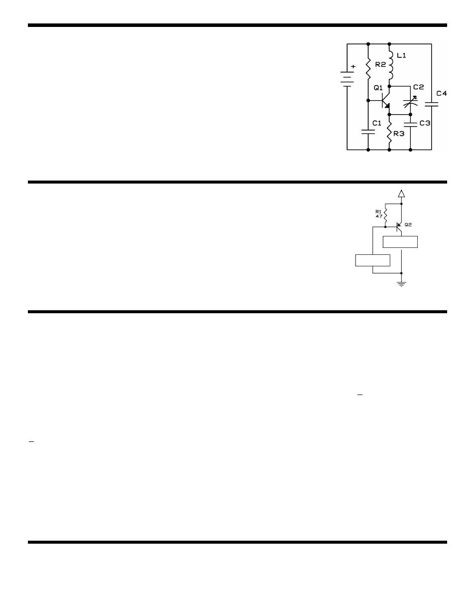
THE RF OSCILLATOR
Figure 2 shows a simplified version of the oscillator circuit. The heart of the circuit
is transistor Q1. It is biased into conduction by resistor R2. In the collector of the
transistor is a tuned circuit consisting of inductor coil L1 and capacitors C2, C3
and C4. A tuned circuit resonates at a natural resonant frequency. In our case,
the resonant frequency is in the FM radio band, between 88 and 108 megahertz
(MHz). Capacitor C2 is a variable capacitor. By adjusting C2, you can change the
frequency of oscillation.
To get an oscillator to work, you need positive feedback with a voltage gain greater
than one. Transistor Q1 provides the gain and capacitor C2 gives the positive
feedback. Under these conditions, transistor Q1 will oscillate at the natural
frequency of the tuned circuit. Capacitor C1 bypasses the base of the transistor,
and capacitor C4 blocks the DC voltage from the tuned circuit.
THE VOICE AMPLIFIER
Figure 3 shows the basic circuit of the voice amplifier. It consists of transistor Q2
and resistor R1. The output load for this amplifier is the oscillator circuit. This is a
unique arrangement and we shall explain why in the next section.
The positive voltage for the amplifier is supplied by the telephone line. When the
telephone receiver is off the hook, 6-8 volts appear across the green and red
telephone wires. This causes a current flow through resistor R1, which turns on
transistor Q2. Any voice frequencies on the telephone line will be amplified at the
output of the collector of Q2.
Figure 2
Figure 3
L1
Oscillator
Green
Wire
Positive
Voltage
Telephone
Red Wire