Elenco Space War Gun User Manual
Page 6
COMPONENT CHECK
1. Be sure that all components have been mounted in their correct places.
2. Make sure that C1, the electrolytic capacitor is mounted correctly. The negative lead should be in the hole
as shown on the top legend.
3. Have LEDs D1 and D2 been installed correctly? The flat side of their bodies should be in the same direction
as marked on the top legend. If the LEDs are in backwards, they will not light.
4. Pay close attention to the red and black wires of the battery snap. The red wire should be installed in the
positive (+) hole and the black wire in the negative (–) hole. Snap in a fresh 9-volt battery.
TROUBLESHOOTING
Contact Elenco Electronics if you have any problems. DO NOT contact your place of purchase as they will not
be able to help you.
1. One of the most frequently occurring problems is poor solder connections. Tug slightly on all parts to make
sure that they are indeed soldered.
2. All solder connections should be shiny. Resolder any that are not.
3. Solder should flow into a smooth puddle rather than a round ball. Resolder any connection that has formed
into a ball.
4. Have any solder bridges formed? A solder bridge may occur if you accidentally touch an adjacent foil by
using too much solder or by dragging the soldering iron across adjacent foils. Break the bridge with your
soldering iron.
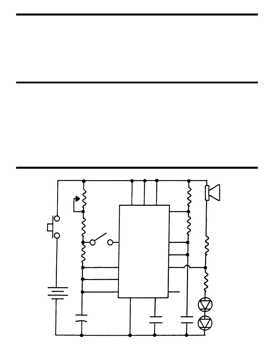
SCHEMATIC DIAGRAM
-5-
S1
B1
+
+
C1
220
μF
7
11
3
8
12
S2
13
R2
100
Ω
R1
100
Ω
P1
50k
Ω
4
10
14
R3
1k
Ω
1
2
6
5
9
IC1
556
R4
56k
Ω
SPK1
R5
47
Ω
R6
560
Ω
.01
μF
.01
μF
C2
C3
D1
D2