Circuit operation, The 555 ic timer, Voltage controlled oscillator (vco) – Elenco Space War Gun User Manual
Page 3: Figure 2 figure 3b figure 3a, Figure 1
-2-
CIRCUIT OPERATION
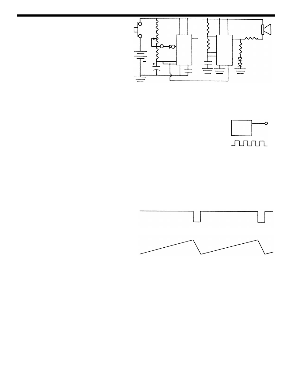
Figure 1 shows the circuit of the Space War
Gun. It consists of two 555 integrated circuits
(IC) packaged in one IC 556. A 555 timer is well
known for its ability to operate as an astable
multivibrator oscillator. This oscillator can put
out a square wave or pulses depending on the
value of the resistors. The first 555A IC
oscillates at about 2000 cycles per second. The
555A IC drives the 555B IC to give the weird
space sounds.
THE 555 IC TIMER
Let’s study the right side of Figure 1 which shows the 555B circuit. Resistor R3, R4 and
capacitor C3 control the frequency of oscillation of this circuit. Capacitor C3 charges
through resistors R3 and R4, but discharges through resistor R4 and the IC. Since the
value of R3 and R4 are 1k
Ω and 56kΩ respectively, their total value equals 57kΩ. Thus,
C3 charges through 57k
Ω and discharges through 56kΩ. The charge and discharge time
is about equal. The output at pin 5 will be a square wave as shown in Figure 2. The
frequency of oscillation will be around 2,000 cycles per second. If a speaker is connected
to output pin 5, we will hear the 2,000 cycle tone. When the two LEDs are connected to
this output, they will light whenever the output goes positive. Resistor R6 is added to limit
the current in the LEDs. Resistor R5 is added to limit the current in the speaker.
The operation of the 555A IC differs quite a bit from the 555B IC. Note the value of the capacitor C1, it is 220
μF
or 22,000 times bigger than the .01
μF used in the 555B. This means that the frequency of oscillation will be
much lower. Also, resistor P1 is made a 50,000
Ω variable. Resistor R2 is only 100Ω. Thus, the charge time
on capacitor C1 is through the 100
Ω. With the pot at the maximum position, the charge to discharge will be
500:1. Figure 3A shows the pulse as it appears in
the output in 9. Figure 3B shows the voltage across
capacitor C1. By varying the value of P1, the
distance between the pulses will be made shorter of
the frequency will be increased. At the minimum
position, the charge time will be twice the discharge
time (200
Ω versus 100Ω). Thus, varying P1 will
change the frequency between .1 cycles to 45
cycles. This change in frequency adds to the effects
of the Space War Gun.
VOLTAGE CONTROLLED OSCILLATOR (VCO)
The 555 timer is designed to allow the output frequency to be varied by changing the DC voltage. If we raise
the voltage at the 555B input pin 3, the output will decrease in frequency. In the Space Gun design, the VCO
of the 555B is connected to the voltage across capacitor C1. This voltage is sawtooth in shape as shown in
Figure 3B. As this voltage increases, the pitch-frequency of the 555B timer is constantly changing at a rate
determined by the voltage amplitude of the 555A timer.
Figure 2
Figure 3B
Figure 3A
Clock Circuit
555
Output
5
Low
R1
S1
P1
S2
R2
8
13
C1
B1
9V
12
7
11
C2
555A
555B
4
10
9
N.C.
R4
C3
2
7
6
1
R3
14
5
10
R5
R6
D1
D2
3
SPK
+
Figure 1