Assemble components to the pc board – Elenco Space War Gun User Manual
Page 5
-4-
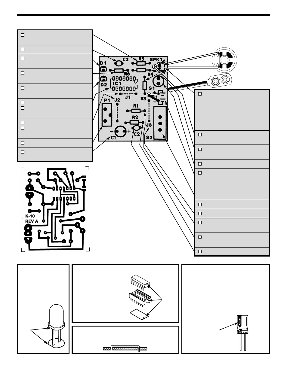
ASSEMBLE COMPONENTS TO THE PC BOARD
R5 - 47
Ω 5% 1/4W Resistor
(yellow-violet-black-gold)
C3 - .01
μF (103) Discap
D1 - LED Diode Red
(see Figure A)
R6 - 560
Ω 5% 1/4W Resistor
(green-blue-brown-gold)
D2 - LED Diode Green
(see Figure A)
IC1 - IC Socket 14-pin
IC1 - 556 Integrated Circuit
(see Figure B)
J1 - Jumper Wire
J2 - Jumper Wire
(see Figure C)
P1 - Trim Pot
C1 - 220
μF Electrolytic Capacitor
(see Figure D)
Figure D
Electrolytic capacitors have polarity. Be
sure to mount them with the negative (–)
lead (marked on side) in the correct
hole.
Warning: If the capacitor is connected
with incorrect polarity, it may heat up
and either leak or cause the capacitor to
explode.
Polarity Marking
SPK1 - Speaker
Strip 1/8” of insulation off of both ends of
the 4” wires. Solder a wire to each lug of
the speaker and then insert the other end
of the wires through the hole in the PC
board as shown. Solder the wires in the
position shown on the top legend. Cut off
the excess leads.
R4 - 56k
Ω 5% 1/4W Resistor
(green-blue-orange-gold)
R3 - 1k
Ω 5% 1/4W Resistor
(brown-black-red-gold)
S1 - Push Button Switch
B1 - Battery Snap -
Insert the red
and black wire through the hole in the
PC board as shown. Install the red
wire into the positive (+) hole and the
black wire into the negative (--) hole.
Solder and cut off the excess leads.
S2 - Slide Switch
J3 - Jumper Wire (see Figure C)
R1 - 100
Ω 5% 1/4W Resistor
(brown-black-brown-gold)
R2 - 100
Ω 5% 1/4W Resistor
(brown-black-brown-gold)
C2 - .01
μF (103) Discap
Figure A
Mount the LED onto the
PC board with the flat
side of the LED in the
same direction as
marked on the PC board.
Flat
Figure B
Insert the IC socket into the
PC board with the notch in
the direction shown on the
top legend. Solder the IC
socket into place. Insert
the IC into the socket with
the notch in the same
direction as the notch on
the socket.
Figure C
Use an excess lead to form a jumper wire. Bend the
wire to the correct length and mount it to the PC board.
Foil Side of PC Board
Notch