Schematic diagram fm-88k, Fm radio highlights – Elenco AutoScan Fm Radio Kit User Manual
Page 6
-10-
TESTING - SECTION 1
In this test, you will produce a clicking sound by
shorting the bottom volume control pin to ground using
your finger.
r
1. Install a new 9V battery into the battery holder.
Turn the power switch on and turn the knob
fully clockwise. The LED should light.
If LED does not light;
Make sure the diode D2 and LED D3,
capacitor C2, and U2 are mounted in the
correct position as marked on the PC
board.
Check that resistor R1 is the correct value.
Check if the battery is properly installed in
the battery holder and that the power switch
is operational.
Check capacitors C3 and C17.
r
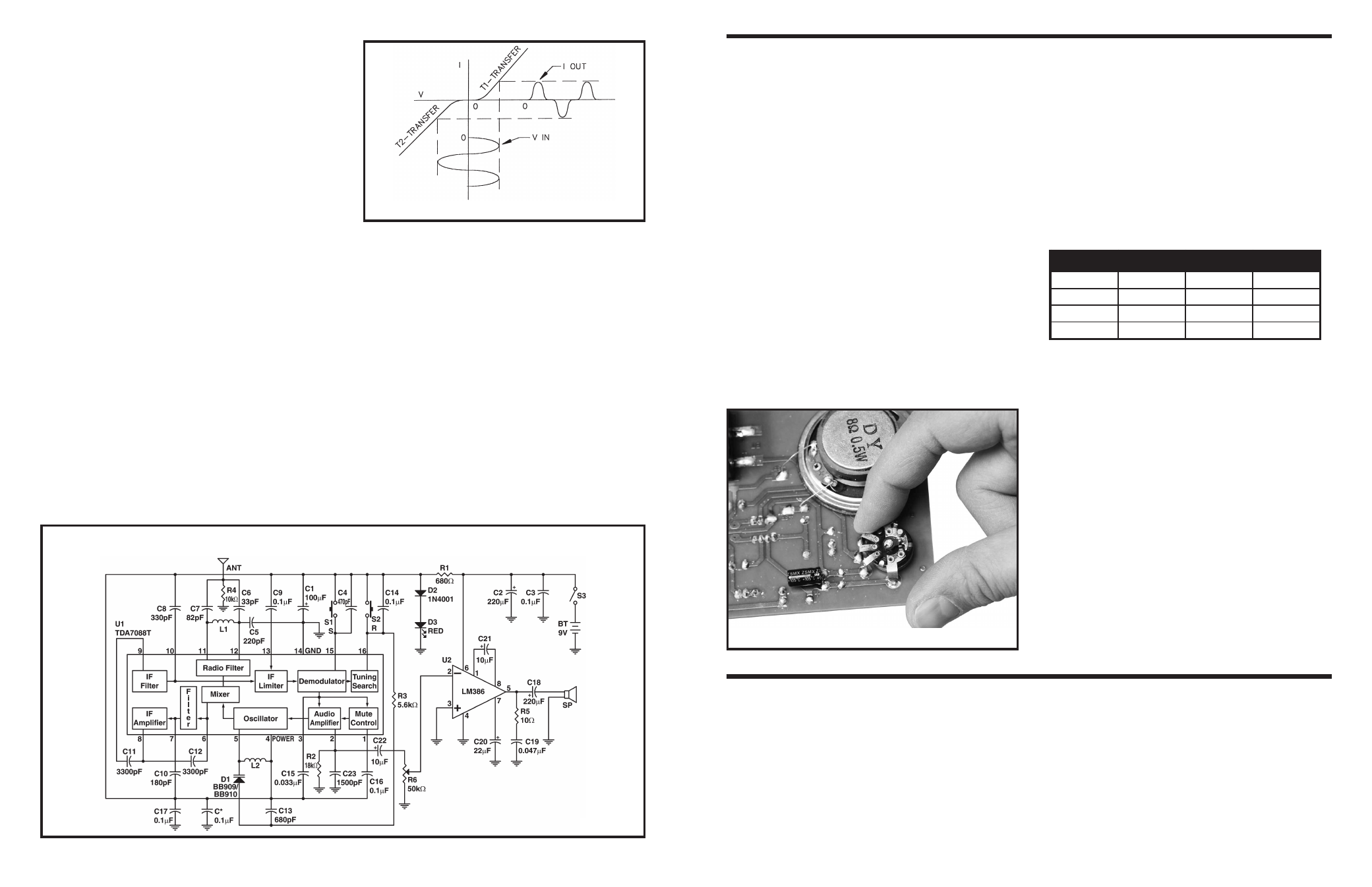
2. Touch the bottom and mounting pins with one
finger as shown in Figure H. You may need to
wet your finger.
You should hear a clicking sound every time the
pins are shorted. If you hear no sound then;
r
Check that U2 and C18 are installed in the
correct position as marked on the PC
board.
r
Check the potentiometer R6 and the
speaker. Make sure the speaker’s wires are
soldered correctly and not shorting
together.
Voltage reference chart for U2 LM386
Voltage Regulator Circuit
Check the following voltages.
r
1. Voltage across D2 and D3 should be 2.6V
r
2. Voltage across the LED D3 should be 1.9V.
Turn the power switch off and remove the battery from
the holder.
Pin #
Voltage
Pin #
Voltage
1
1.3
5
4.5
2
0
6
9.0
3
0
7
4.5
4
0
8
1.3
Figure H
-5-
a class B amplifier (transistor on for ½ cycle), the
maximum theoretical efficiency is 0.785 or 78.5%.
Since transistor characteristics are not ideal in a pure
class B amplifier, the transistors will introduce
crossover distortion. This is due to the non-linear
transfer curve near zero current or cutoff. This type
distortion is shown in Figure 1. In order to illuminate
crossover distortion and maximize efficiency, the
output transistors of the audio amplifier are biased
on for slightly more than ½ of the cycle, known as
class AB. In other words, the transistors are working
as class A amplifiers for very small levels of power
to the speaker, but they side toward class B
operation at lager power levels.
Figure 1
SCHEMATIC DIAGRAM FM-88K
Figure 2
CIRCUIT DESCRIPTION
The model FM-88K is a monophonic FM receiver
made on base TDA7088T IC, as shown in the
schematic diagram (Figure 2). The circuit contains
two ICs, speaker, two coils, and a few other
components. The IC TDA7088T (U1) (depending on
the manufacturer, may be type SC1088, SA1088,
CD9088, D7088, or YD9088) is a surface mount,
bipolar integrated circuit of a proper FM
“superheterodyne” receiver. The IC contains a
frequency-locked-loop (FLL). The station signals led
from the telescopic antenna to the input circuit
consists of L1, C5, C6 and C7. It is a parallel
oscillatory circuit damper with resistor R4. Inside IC
signals are led into the mixer, where they are given
a new carrier intermediate frequency. The IF
amplifier then follows, amplifying only one of those
signals - the one whose frequency is equal to the IC
- followed by the limiter, the demodulator, mute
control circuit, and pre-audio amplifier. The FM-88K
is an auto-scan radio containing two switches, scan
“S” and reset “R”. Tuning is done by using a varactor
diode (D1) instead of a tuning gang found in most
radios. The varactor’s capacitance is changed by
varying the DC voltage supplied to its anode over
resistor R3.
This is how the tuning is performed:
When switch S1 “S” (Scan) is pressed and released,
a positive voltage is applied to the input of the Tuning
Search circuit pin 16. Capacitor C14 starts charging
and the voltage on pin 16 increases. This voltage is
FM RADIO HIGHLIGHTS
1. The FM broadcast band covers the frequency
range from 88MHz to 108MHz.
2. FM signals are usually limited to line a sight.
3. Audio signals up to 15kHz are transmitted on the
FM carrier.
4. The amount that the RF carrier changes frequency
is determined by the amplitude of the modulating
signal.
5. The number of times the carrier frequency
changes in a period of time is exactly equal to the
audio frequency.
6. The bandwidth assigned for FM is 200kHz.