Introduction, Description and features, Assemble components to the pc board – Elenco AutoScan Fm Radio Kit User Manual
Page 5
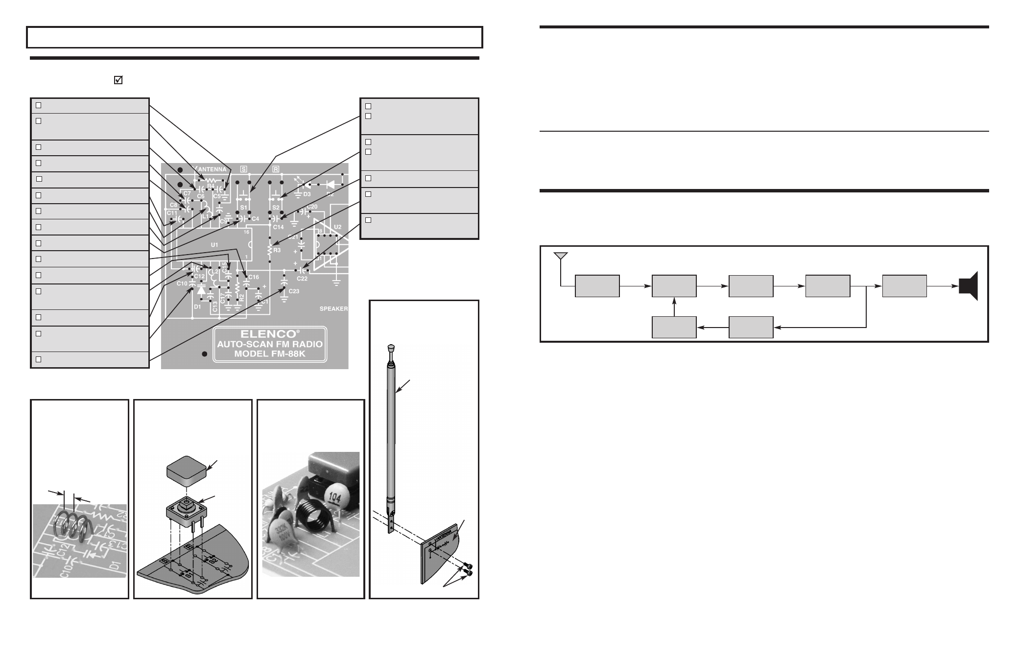
INTRODUCTION
The FM (Frequency Modulation) band covers 88 –
108 MHz. There are signals from many radio
transmitters in the band inducing signal voltages in
the area. Below is a block diagram of a basic
SUPERHETERODYNE FM radio:
• Electronic auto-scan FM RADIO FM-88K is a receiver
for searching FM stations
• Operated by two push button switches
• Frequency range: (88 – 108) MHz
• High sensitivity
• Volume control of 8
Ω
speaker
• Telescopic antenna
• LED power ON indicator
• Power source 9V battery with ON/OFF power switch
DESCRIPTION AND FEATURES
-4-
RF
AMPLIFIER
OSCILLATOR
IF
AMPLIFIER
AFC
MIXER
DETECTOR
AUDIO
AMPLIFIER
Speaker
FM RF AMPLIFIER, MIXER, OSCILLATOR
The RF amplifier selects and amplifies a desired
station from many. It is adjustable so that the
selection frequency can be altered, also known as
tuning. The selected frequency and the output of an
Oscillator are applied to the mixer, forming a
frequency changer circuit. The RF amplifier and the
oscillator are the only two resonant circuits that
change when the radio is tuned for different stations.
Since a radio station may exist 10.7MHz above the
oscillator frequency, it is important that the RF stage
rejects this station and selects only the station
10.7MHz below the oscillator frequency.
The frequency of the undesired station 10.7MHz
above the oscillator is called the Image Frequency.
Since the FM receiver has an RF amplifier, the image
frequency is reduced significantly. The output from
the mixer is the Intermediate Frequency (IF), a fixed
frequency of 10.7MHz. The IF signal is fed into the
IF amplifier. The advantage of the IF amplifier is that
its frequency and bandwidth are fixed, no matter
what the frequency of the signals. The IF amplifier
increases the amplitude, while also providing
selectivity. Selectivity is the ability to “pick out” one
station while rejecting all others.
FM DETECTOR
The amplified IF signal is fed to the detector. This
circuit recovers the audio signal and discards the IF
carrier. Some of the audio is fed back to the oscillator
as an Automatic Frequency Control (AFC) voltage.
This ensures that the oscillator frequency is stable in
spite of temperature, voltage, and other effects
changes. If this occurs, the center frequency of
10.7MHz will not be maintained. AFC is used to
maintain the 10.7MHz center frequency. When the
local oscillator drifts, the radio detector will produce
a DC (direct current) “correction” voltage. This signal
is fed to a filter network that removes the audio so
that pure DC voltage is produced and changes the
frequency of oscillation of the local oscillator.
AUDIO AMPLIFIER
The audio amplifier increases the audio power to a
level sufficient to drive an 8
Ω
speaker. To do this, DC
from the battery is converted by the amplifier to AC
(alternating current) in the speaker. The ratio of the
power delivered to the speaker and the power taken
from the battery is the efficiency of the amplifier. In
a class A amplifier (transistor on over entire cycle),
the maximum Theoretical efficiency is 0.5 or 50%. In
-11-
ASSEMBLE COMPONENTS TO THE PC BOARD
Place a check mark in the box provided next to each step to indicate that the step is completed.
SECTION 2
C5 - 220pF Discap (221 or 220)
R4 - 10k
Ω
5% 1/4W Res.
(brown-black-orange-gold)
C6 - 33pF Discap (33)
C7 - 82pF Discap (82)
C8 - 330pF Discap (331 or 330)
C11 - 3300pF Discap (332)
L1 - Coil 6-turn (see Figure K)
C9 - 0.1
μ
F Discap (104)
C4 - 470pF Discap (471 or 470)
C16 - 0.1
μ
F Discap (104)
C15 - 0.033
μ
F Discap (333)
L2 - Coil, 4-turn
(see Figure I)
C12 - 3300pF Discap (332)
C10 - 180pF Discap
(181 or 180)
C23 - 1500pF Discap (152)
r Install FM antenna
Mount the antenna to the PC board
using two M2 x 5mm screws as
shown.
Figure K
Mount the 6-turn coil to the PC
board as shown. Solder and cut
off excess leads.
Figure J
Mount the push button switch flush to
the PC board and solder into place.
Attach the plastic button cap to the
switch by snapping it into place.
FM antenna
Legend side of PC board
M2 x 5mm Screws
Button cap
Push button
switch
S1 - Push button switch
S1 - Cap yellow
(see Figure J)
S2 - Push button switch
S2 - Cap red
(see Figure J)
C14 - 0.1
μ
F Discap (104)
R3 - 5.6k
Ω
5% 1/4W Res.
(green-blue-red-gold)
C22 - 10
μ
F Electrolytic
(see Figure D)
Figure I
Using a spacer, create three
1/16” gaps in the 4-turn coil as
shown. Mount the coil to the
PC board as shown. Solder
and cut off excess leads.
1/16” gap
Note:
Capacitors C21 and C* are not used.
The ELENCO
®
FM-88K Kit is a monophonic, two-IC, FM
(frequency modulation) receiver designed to receive FM
signals in the frequency range (88-108MHz). It uses
electronic auto-scan to search for FM stations. This scan
system is done with two button switches - one switch scans
up, the other resets to the start of the tuning position.
The unique design of this radio kit allows you to place the
parts over the corresponding symbols in the schematic
drawing on the surface of the printed circuit board. This
technique maximizes the learning process, while keeping
the chance of assembly error at a minimum.
To simplify troubleshooting the FM radio, it is constructed
in two sections (Audio and RF). There are two IC’s, one
for the audio section, the other for the RF. The RF IC is
surface mounted (SM-IC), pre-installed on the high quality
printed circuit board.