You will need, Identifying resistor values, Metric units and conversions – Elenco AutoScan Fm Radio Kit User Manual
Page 4: Identifying capacitor values
-3-
• 9V Battery
• 25 or 30 watt Soldering Iron
• Small Phillips and Slotted Screwdrivers
• Long Nose Plier
• Side Cutters
IDENTIFYING RESISTOR VALUES
Use the following information as a guide in properly identifying the value of resistors.
BANDS
METRIC UNITS AND CONVERSIONS
Abbreviation Means Multiply Unit By Or
p Pico .000000000001 10
-12
n nano .000000001 10
-9
μ
micro .000001 10
-6
m milli .001 10
-3
– unit 1 10
0
k kilo 1,000 10
3
M mega 1,000,000 10
6
1. 1,000 pico units
= 1 nano unit
2. 1,000 nano units
= 1 micro unit
3. 1,000 micro units
= 1 milli unit
4. 1,000 milli units
= 1 unit
5. 1,000 units
= 1 kilo unit
6. 1,000 kilo units
= 1 mega unit
You Will Need:
IDENTIFYING CAPACITOR VALUES
Capacitors will be identified by their capacitance value in pF (picofarads), nF (nanofarads), or
μ
F (microfarads).
Most capacitors will have their actual value printed on them. Some capacitors may have their value printed in
the following manner. The maximum operating voltage may also be printed on the capacitor.
Second Digit
First Digit
Multiplier
Tolerance
*
Note:
The letter “R”
may be used at times
to signify a decimal
point; as in 3R3 = 3.3
103K
100V
The letter M indicates a tolerance of +20%
The letter K indicates a tolerance of +10%
The letter J indicates a tolerance of +5%
Maximum Working Voltage
The value is 10 x 1,000 =
10,000pF or .01
μ
F 100V
*
Electrolytic capacitors have a positive
and a negative electrode. The negative
lead is indicated on the packaging by
a stripe with minus signs and possibly
arrowheads.
Warning:
If the capacitor is
connected with
incorrect polarity, it
may heat up and
either leak, or cause
the capacitor to
explode.
Polarity
Marking
BAND 1
1st Digit
Color
Digit
Black
0
Brown
1
Red
2
Orange
3
Yellow
4
Green
5
Blue
6
Violet
7
Gray
8
White
9
BAND 2
2nd Digit
Color
Digit
Black
0
Brown
1
Red
2
Orange
3
Yellow
4
Green
5
Blue
6
Violet
7
Gray
8
White
9
Multiplier
Color
Multiplier
Black
1
Brown
10
Red
100
Orange
1,000
Yellow
10,000
Green
100,000
Blue
1,000,000
Silver
0.01
Gold
0.1
Resistance
Tolerance
Color
Tolerance
Silver
±10%
Gold
±5%
Brown
±1%
Red
±2%
Orange
±3%
Green
±0.5%
Blue
±0.25%
Violet
±0.1%
1
2
Multiplier
Tolerance
Multiplier
For the No.
0
1
2
3
4
5
8
9
Multiply By
1
10
100
1k
10k 100k .01
0.1
-12-
TESTING - SECTION 2
Voltage reference chart for U1 TDA 7088T (turn radio
on and press reset).
Test
Verify that FM signals are present in your location by
listening to another FM radio placed near the FM-88K.
1. Install fresh 9V battery into holder.
2. Bend the antenna to vertical position and
adjust for maximum length.
3. Turn ON power switch (rotate clockwise until a
“click” is heard). RED LED should light. Turn
the VOLUME CONTROL potentiometer to
middle position (comfortable level).
4. Press and release “RESET” (
R
) button.
Press and release the “SCAN” (
S
) button once or
a couple of times; a station should be heard. Press
and release “SCAN” button again; the radio should be
automatically searching for other broadcast station.
When you press the “SCAN” button in several times,
there should be other broadcast stations coming
before the HIGH-END frequency (FM106-108MHz).
If test fails;
Make sure that all of the parts are placed in
their correct position. Check if the orientation
of D1 is correct.
Short pins 2 and 14 of U1 several times using
a wire. If you don’t hear tapping from the
speaker, check U1, capacitors C22 and C23,
resistor R2, and potentiometer R6.
Alignment
The first time “SCAN” button is pressed, the radio
should start at the bottom end of the FM band (88-90
MHz). You may need to press the SCAN button a
couple of times. If it doesn’t tune to the low end, you
will need to adjust the coil.
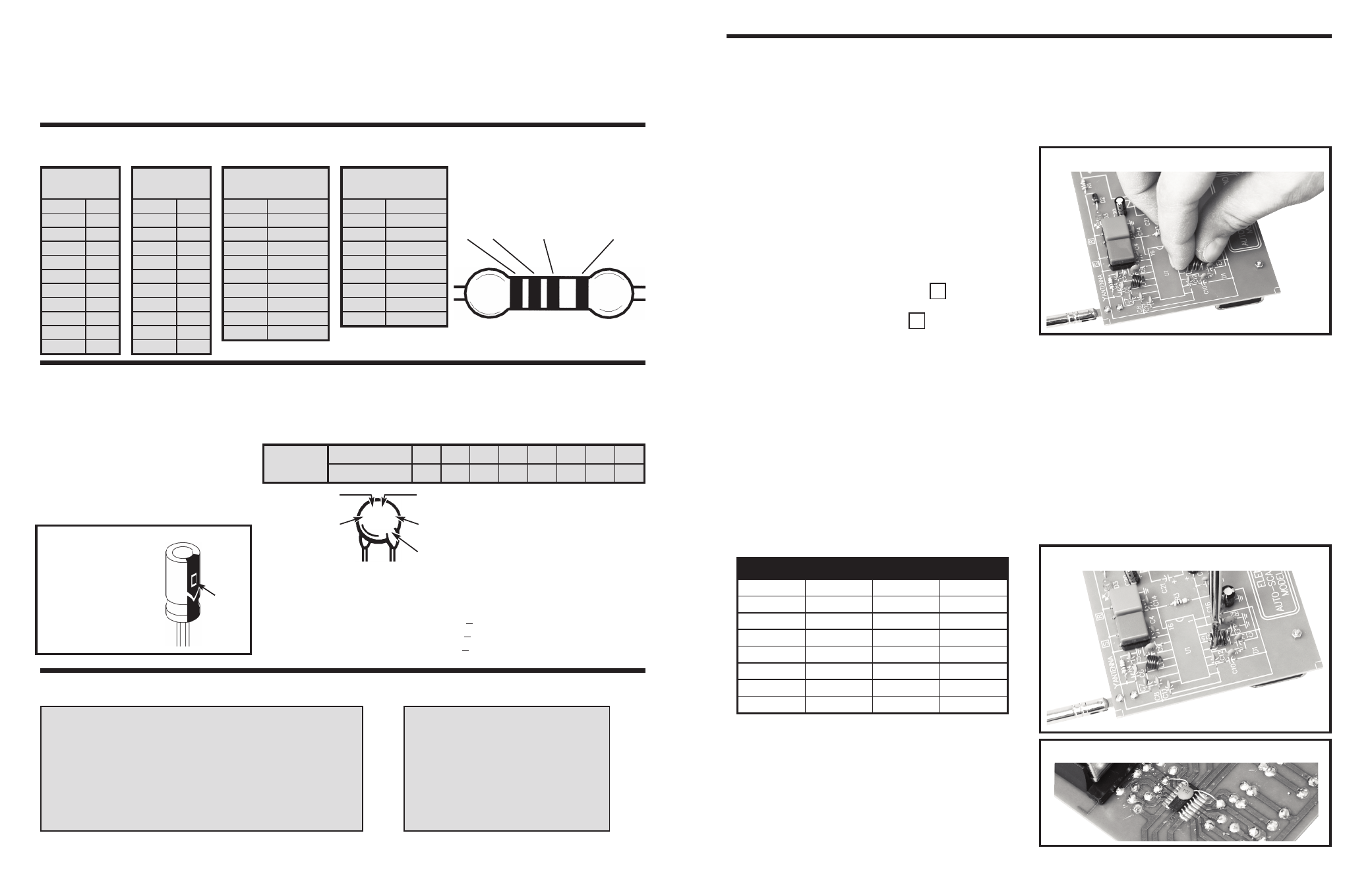
If the radio is receiving station frequencies higher than
90MHz after pressing the “RESET” button, you will
need to adjust coil L2 to a higher value (by making the
gap between the coils smaller as shown in Figure L).
Carefully press the coils of L2 together.
If the radio is receiving station frequencies smaller than
87MHz after pressing the “RESET” button (to receive
regular FM stations you need to press the “SCAN”
button several times), then you will need to adjust the
L2 coil to a smaller value (carefully slide a small
screwdriver between coils to get the spacing shown in
Figure M).
If sound is not clear;
Install capacitor C* onto the copper side of the
PC board as shown in Figure N.
If you need more gain (up to 200), install
capacitor C21 (10
μ
F) as shown in Figure D.
Pin #
Voltage
Pin #
Voltage
1
2.4
9
1.9
2
1.3
10
1.9
3
2.2
11
0.9
4
2.6
12
0.9
5
2.6
13
1.8
6
2.0
14
0
7
1.9
15
1.7
8
1.2
16
2.1
Figure L
Figure M
Figure N