Assemble components to the pc board, Figure d, Figure e – Elenco Digital Roulette Kit User Manual
Page 9: Figure f, Figure g, Led spacer
-8-
C1 - .02
µ
F or .022
µ
F
(203 or 223) Discap
R12 - 2.2M
Ω
5% 1/4W Resistor
(red-red-green-gold)
R9 - 10k
Ω
5% 1/4W Resistor
(brown-black-orange-gold)
R13 - 47k
Ω
5% 1/4W Resistor
(yellow-violet-orange-gold)
R14 - 330k
Ω
5% 1/4W Resistor
(orange-orange-yellow-gold)
D37 - LED Green
(see Figure A)
C2 - .0033
µ
F (332) Mylar Cap.
(see Figure F)
D40 - 1N4148 Diode
(see Figure E)
C3 - 1
µ
F Electrolytic
(see Figure D)
U2 - 14-pin Socket
U2 - 4069 Integrated Circuit
(see Figure B)
D39 - 1N4148 Diode
(see Figure E)
D41 - 1N4001 Diode
(see Figure E)
R19 - 1.5k
Ω
5% 1/4W Resistor
(brown-green-red-gold)
R23 - 1.8M
Ω
5% 1/4W Resistor
(brown-gray-green-gold)
R20 - 100k
Ω
5% 1/4W Resistor
(brown-black-yellow-gold)
R22 - 1k
Ω
5% 1/4W Resistor
(brown-black-red-gold)
D43 - 1N4001 Diode
(see Figure E)
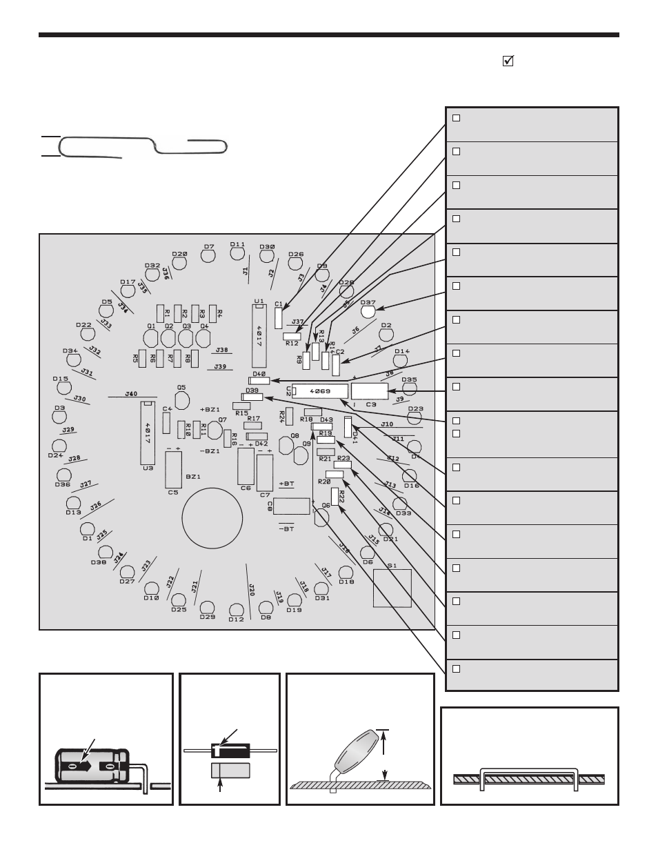
ASSEMBLE COMPONENTS TO THE PC BOARD
Identify and install the following parts as shown. After soldering each part, place a check in the box provided.
Space the LED’s with a paper clip (use size shown below) so that they are 1/4” off of the PC board.
Figure D
Electrolytic capacitors have polarity.
Be
sure to mount them with the negative (–)
lead (marked on the side) in the correct
hole.
Bend the capacitor 90
O
as shown
below.
Figure E
Mount the diode with the band
in the same direction as marked
on the PC board.
Band
Polarity Marking
PC Board Marking
Figure F
Mount the mylar capacitor at a 45
O
angle to the
PC board with 0.35” maximum height as shown
below.
.35”
max.
Figure G
Use the bare wire supplied to form a jumper wire.
Bend the wire to the correct length and mount it to
the PC board.
LED Spacer
(Actual Size)
1/4”