Introduction, Theory of operation, The block diagram – Elenco Digital Roulette Kit User Manual
Page 4: The timer, Figure 1 figure 2, Schematic diagram a b c
-3-
INTRODUCTION
Electronic Roulette (roo-let) replaces the ivory ball
with a circuit of flashing light emitting diodes (LED’s).
Red LED’s are arranged in a circle next to a black or
red number and two green LED’s are positioned next
to “0” and “00”. When the switch is pushed, the LED’s
light one after another, in a sequence that represents
the movement of the ivory ball. The number next to
the lit LED when movement stops is the winning
number. During movement, the sound of a bouncing
ball is generated. If the switch is not pressed again,
the circuits will automatically turn off, to conserve the
battery power. A constant tone will alert you to check
your number before automatic shut down.
THEORY OF OPERATION
THE BLOCK DIAGRAM
The function of many of the circuits will be presented
in the form of an analogy (similar operation, but
easier-to-understand system). In this manner, the
operation of a circuit can be explained without the
use of mathematics and equations.
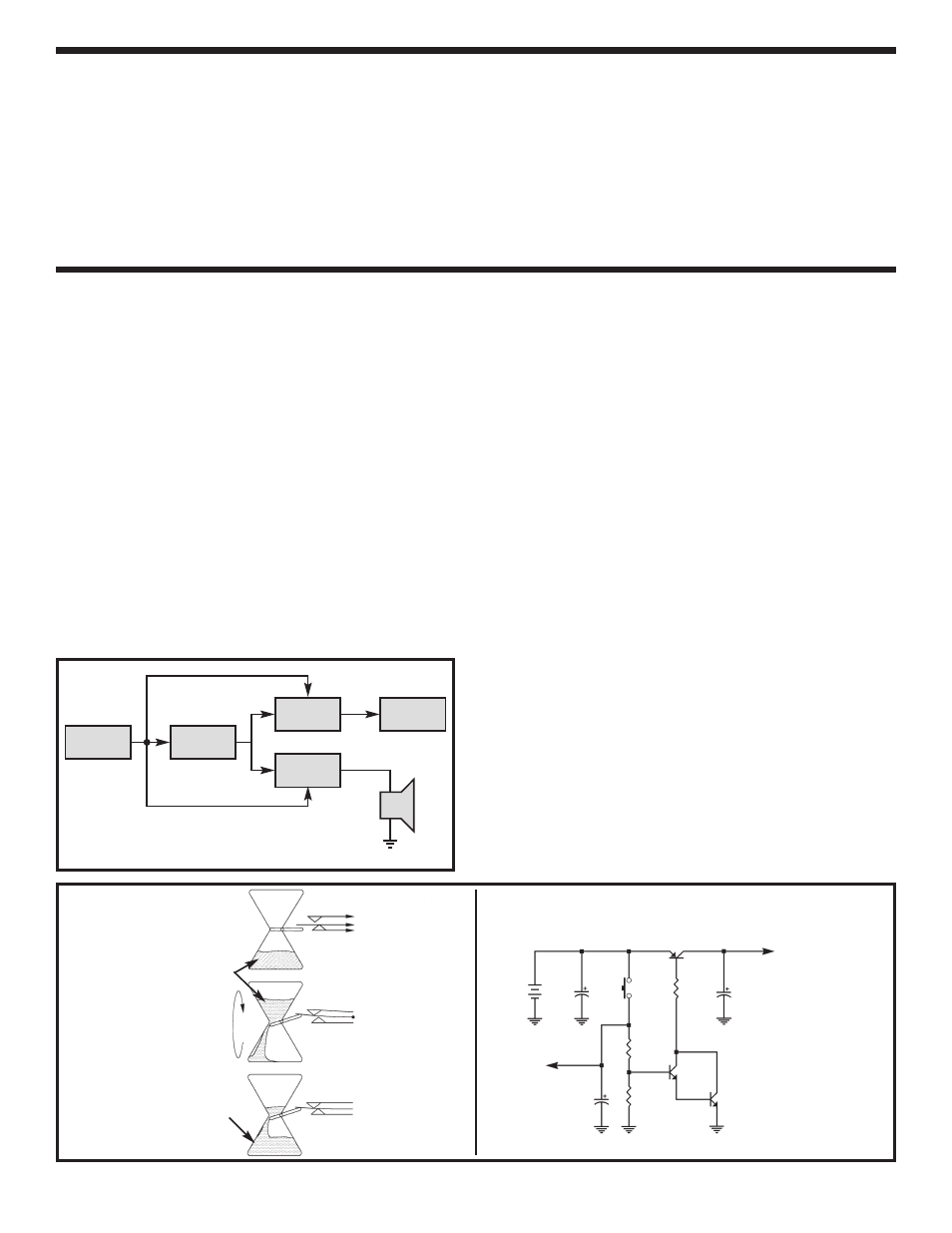
Figure 1 shows a Block Diagram of the Electronic
Roulette circuits. The Timer circuit is used to turn all
the other circuits on and off. The Pulse Generator
makes pulses that create the sound and force the
ring counter to move the position of the lit LED. The
Sound Circuit generates the sound of a bouncing
ivory ball, and a warning tone a few seconds before
power down. The Ring Counter lights each LED in a
circular sequence. The LED’s represent the position
of the ivory ball.
THE TIMER
When S1, the start button, is pushed, capacitor C7
(Figure 2, Schematic Diagram) is charged to the
battery voltage. This is similar to flipping the “Timer
Glass” shown in Figure 2a to produce the condition
shown in Figure 2b. Just as the sand runs down
holding the lever arm up (Figure 2b), the charges in
th capacitor C7 forces transistors Q6, Q8, and Q9 on.
As long as the lever arm is up in Figure 2b, the other
circuits are powered through the contact C1 on
switch X1. At first, due to the weight of the sand
(similar to capacitor C7 being fully charged), the
contact C2 will open and remain open. Right before
the sand totally runs out (capacitor C7 has lost most
of its charge), the contact C2 will close, as shown in
Figure 2c, and sound an alarm to warn you that the
contact C1 is about to open and turn all the power
off, including the power to the warning circuit.
Eventually all the sand runs out of the “Timer Glass”
(capacitor C7 has discharged) and the power is
turned off (Figure 2a). To make the timer stay on
longer, you could get a bigger “Timer Glass” (larger
capacitor for C7) that holds more sand and replace
the smaller one.
Timer
LED’s
Pulse
Generator
Ring
Counter
Sound
Circuit
Figure 1
Figure 2
Sand
C1
C2
Power for all circuits
Battery
Warning Circuit
Switch X1
C1
C2
Power for all circuits
Battery
Warning Circuit
Switch X1
C1
C2
Power for all circuits
Battery
Warning Circuit
Switch X1
Sand
9V
Battery
BT1
To Warning
Circuit
C7
100
µ
F
R23
1.8M
Ω
R21
4.7M
Ω
Q8
2N3904
Q9
2N3904
C3
1
µ
F
Q6
2N3906
Power for
All Circuits
C8
100
µ
F
S1
R22
1k
Ω
Schematic Diagram
A
B
C